Member
Joined 2009
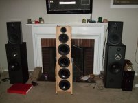
boris81 ... could you explain what's going on with the two different baffle arrangements you have depicted? I noticed the first photo shows the baffle as a solid 1-1/2" ... second photo (with the shortened wings) seems to have a space between the 1-1/2" sandwich ... with an insulation? wrap around the drivers?
I'd listen to the speaker playing music (in room) before settling on a xo point ..(your 200 vs 400hz proposal). While the response might look good on paper ... it might not sound right. This area, to me, seems to be pretty critical for getting vocals to sound natural. ... and there is the room resonance that might show up in the 300hz range. How severe that is will determine how much of a notch a guy needs to implement.
Because of the way my system is developing and the rooms 310hz resonance (pretty strong) , I chose to deal with that notch in the mid/woofer. ... but my bass woofers are separate from the mains ... so the xo is low to begin with. Anyway ... might be something to consider.
I'm sorry for the confusion. I put together a month worth of experiments into a single post.
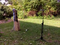
I have 3 types of baffle - naked, large wings and small wings. The naked baffle is pretty straight forward. I wasn't very found of the large wings (aesthetically) and I cut them down so I don't use that configuration anymore. The small wings are tricky because of the different dipole path lengths. I address the problem by equalizing the top and bottom woofer pairs individually.
All configurations have sound absorbing "muflers" attached to the back of the drivers. It's a cotton insulation wrapped around the driver. My directivity plots suggest that they shape the polar response into a supercardioid above 500Hz. The range between 300-700Hz seems to be transitional from cupercardioid to dipole. At low frequencies the radiation is dipole but the rear "bubble" is smaller than the front one, if I may illustrate it this way.
The woofer-midwoofer crossover is indeed challenging, more than I anticipated.
Member
Joined 2009
I'm getting closer to where I want to be in regards to directivity.
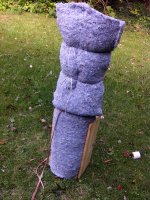
I added more sound absorption in the back. I have the driver mufflers and on top I tied a double layer of UltraTouch cotton insulation.
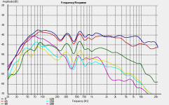
The cardioid pattern looks to be holding up to around 200Hz and then turning to a dipole below. Interestingly I have the mid-woofers crossover at that exact region and I'm a bit disappointed with the performance of the woofer array. I am equalizing the ER18RNX flat to 250Hz and I barely sense any movement from the driver at high volumes. I think the ER18RNX and the Seas DXT in a cardioid leaky enclosure will make a very successful combination with a large conventional monopole woofer in a closed box.
I'm considering removing the top woofer pair and just using the bottom ones. I can't get much bass below 50Hz with these woofers anyway and the harmonic distortion starts rising around 100Hz. The idea is to crossover to a monopole sub at 80Hz and I think one woofer pair of the RS225 should be enough.
The plot shows smoothed 1/3 octave outside measurements at 0-45-90-120-150-180 degrees. The microphone was at tweeter level, 3m away. I'm pretty sure the ripples at 200-700Hz are caused by the floor bounce. I tried to minimize the floor reflection by moving the crossover to 400Hz and just use the bottom woofers but there was no improvement.
I added more sound absorption in the back. I have the driver mufflers and on top I tied a double layer of UltraTouch cotton insulation.
The cardioid pattern looks to be holding up to around 200Hz and then turning to a dipole below. Interestingly I have the mid-woofers crossover at that exact region and I'm a bit disappointed with the performance of the woofer array. I am equalizing the ER18RNX flat to 250Hz and I barely sense any movement from the driver at high volumes. I think the ER18RNX and the Seas DXT in a cardioid leaky enclosure will make a very successful combination with a large conventional monopole woofer in a closed box.
I'm considering removing the top woofer pair and just using the bottom ones. I can't get much bass below 50Hz with these woofers anyway and the harmonic distortion starts rising around 100Hz. The idea is to crossover to a monopole sub at 80Hz and I think one woofer pair of the RS225 should be enough.
The plot shows smoothed 1/3 octave outside measurements at 0-45-90-120-150-180 degrees. The microphone was at tweeter level, 3m away. I'm pretty sure the ripples at 200-700Hz are caused by the floor bounce. I tried to minimize the floor reflection by moving the crossover to 400Hz and just use the bottom woofers but there was no improvement.
Attachments
Member
Joined 2009
First cancellation for these values would be about 230Hz (Floor/Ceiling Reflection Calculator). I'm wondering why the dip varies with angle - did you change the mic distance when rotating the speaker?
Member
Joined 2009
Oh cool, thanks for the link!
I did not intend to change the mic distance when rotating the speaker but the distances might be a few centimeters off. These are rounded with a 1/3octave smoothing.
I assume reflections from the baffle edges, side wings and microphone stand will be much closer to the initial pulse. My computer and chair are about 3m from the microphone and I did not expect will give a large reflection. Next time I'm measuring I will investigate that possibility. There's also a large staircase so I will definitely look into this next time.
I still think the floor is the most likely source.
Member
Joined 2009
very clear bass
I'm listening to the prototype and trying different configurations before I commit to build the actual speakers. The highs and mids are incredible and I highly recommend the ER18RNX - Seas DXT combination although the crossover was difficult.
I wasn't satisfied with the bass performance while I was trying to run the prototype fullrange. I put a highpass filter on the bass array at 60Hz and I crossed over to a bunch of monopole woofers for subbass below that. I don't have a subwoofer at the moment but I have a bunch of speakers and some free amplifier channels so I ran 4 woofers together below 60Hz. The bass of this setup is very clean, the best I ever experienced in a home environment.
I'm not sure exactly what made such a great difference so I need to find out what I'm doing right.
I hope it's not the physical arrangement of the 4 woofers because I plan eventually to just use a single or dual subwoofer(s). I crossed over the by ear because I can't get good measurements that low. I hope I didn't just get lucky and that I could do that again.
Before the woofer array was distorting badly when asked to play deep. I picked the RS225 because I wanted a cheap 8" woofer with large excursion and good bass performance. 10" woofers can obviously do this better but I feel that finding out exactly where the limits are on the ones I have is a good learning exercise. With the lowpass filter in place the prototype speaker sounds very good on it's own although the deep bass is absent.
I want to find out if large excursion is inherently responsible for bass distortion in the cardioid speaker or whether these drivers can do large displacement and still sound clean. The bad sound could also be caused by vibration of the structure.
Attachments
Boris, thank you for your measurements.
I have been experimenting with a baffle similar to yours (TM + woofer array). My baffle was 36cm wide. There was no bass with the slim baffle.
So I added 40cm extensions to the baffle on each side next to the woofers (not U frame wings, just flat baffle extended). Much better bass now.
Your observation that the upper and lower woofers behaved very different has been very useful for me.
In the weekend, I started building a new prototype. The woofers will be in a 2x2 :: set-up on H frames (w=60, h=60, d=40cm). This time I am using 10" woofers instead of 8". And the flat TM baffle will be sitting on top of the H frame with some sorbothane in between.
An important observation with my first test baffle: woofers negatively affect mid range when put on same frame/baffle. Try switching your woofers off and you will see what I mean. In my new designs, the woofers and the rest of the drivers will always be on different baffles/structures.
Many other DIYers have observed this effect actually. But it was still useful to hear the difference myself.
Last edited:
Member
Joined 2009
- Status
- This old topic is closed. If you want to reopen this topic, contact a moderator using the "Report Post" button.
- Home
- Loudspeakers
- Multi-Way
- Waveguie and Cardioid on a Slim Baffle