Hi Folks
I am building a new set of crossovers. I have all the parts but I am unsure of two things and anyone's help would be appreciated.
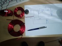
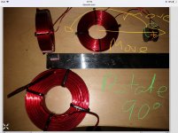
Question 1. How do I lay out the inductors to minimize interference. I have attached the circuit diagram and what the inductors look like. Can some be stacked?
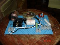
Question 2 . How does one pyhsically attach the circular inductors to a circuit board? Can you glue them on with a glue gun? May not be strong enough for any mounted on edge..
Thanks for any and all help. Regards
I am building a new set of crossovers. I have all the parts but I am unsure of two things and anyone's help would be appreciated.
Question 1. How do I lay out the inductors to minimize interference. I have attached the circuit diagram and what the inductors look like. Can some be stacked?
Question 2 . How does one pyhsically attach the circular inductors to a circuit board? Can you glue them on with a glue gun? May not be strong enough for any mounted on edge..
Thanks for any and all help. Regards
Attachments
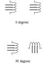
Coils have a magnetic field. Neighbouring coils will be affected by this magnetic field. To minimize that they should be mounted at 90 deg. to each other. Obviously, if it is a 5 Watt speaker, the coils could be a lot closer to each other than in a 100W unit.
To hold the coils in place I would use ty-raps until I am happy with the performance and after that, use contact cement liberally to prevent rattling (the Xover beeing in the box). You are screwed though, should you want to make some changes later on... E
To hold the coils in place I would use ty-raps until I am happy with the performance and after that, use contact cement liberally to prevent rattling (the Xover beeing in the box). You are screwed though, should you want to make some changes later on... E
Agree with mickeymoose about the 90 deg. to each other mounting - and the further away from each other the better. If you use perf board or drill a couple of holes of suitable size you can use plastic tie wraps to secure them to the board along with some silicon to provide a bit of mechanical dampening.
Attachments
I am having trouble understanding what 90 degrees to each other means, and how would you line them all up if there are 4 inductors involved as in my case.
Thanks
Jim
Take two inductors and place them together as if you were going to slide a pole or stick through their center area void or hole.
Now take one and rotate it 90 degrees - presto!!!

Attachments
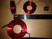
My comments will almost assuredly result in flames but I hate to see people doing unnecessary things or worrying unnecessarily. If you are not limited on room for the crossover, you can mount all inductors flat on their sides, rather than stand some of them up on edge with a 90-degree orientation. In fact, as long as you have at least 2" between the outer perimeters of adjacent coils, they all can still be mounted on their sides. With 2" of spacing the "crosstalk" between coils is well under 1%, about 0.3% IIRC. If space is limited, however, standing some on edge and rotating them 90 degrees is the way to go.
Paul
Paul
Clarification...
I forgot to say my comments applied only to air-core inductors.
Paul
I forgot to say my comments applied only to air-core inductors.
Paul
My comments will almost assuredly result in flames but I hate to see people doing unnecessary things or worrying unnecessarily. If you are not limited on room for the crossover, you can mount all inductors flat on their sides, rather than stand some of them up on edge with a 90-degree orientation. In fact, as long as you have at least 2" between the outer perimeters of adjacent coils, they all can still be mounted on their sides. With 2" of spacing the "crosstalk" between coils is well under 1%, about 0.3% IIRC. If space is limited, however, standing some on edge and rotating them 90 degrees is the way to go.
Paul
Placement of coils in crossover networks
An externally hosted image should be here but it was not working when we last tested it.
Exactly my point...
Troels placed a pair of 0.56 mH inductors different distances apart and with different orientations, then measured how much the two inductances totaled when wired in series. With a very wide spacing and both inductors laid flat, like in the first example of 20 cm CTC or even wider, the sum was 1.144 mH with no ill effects. The problem is with his "problematic" label for the second scenario with the CTC spacing at 10 cm. The measured inductance was 1.137 mH, and if you "do the math" you'll find this "error" amounts to 0.6%. Oh, surely that would sound horrible, right? NOT!!! It's ludicrous to think this small amount of mutual inductance percentage-wise will have any audible ill effects, and barely measurable to boot. Still, if one has the room, it makes good sense to spread the inductors apart as far as possible, but no one should be at all reluctant to space them as close as 2" perimeter-to-perimeter. Before anyone asks, that 0.3% cross-talk factor I mentioned in my first post came from an article published in Speaker Builder a number of years ago, and my memory was correct, and it differs from what Troels showed because of the difference in CTC and perimeter-to-perimeter setups.
Paul
Placement of coils in crossover networks
An externally hosted image should be here but it was not working when we last tested it.
I do not believe the problem with poor placement of coils is in the change of inductance but in cross-coupling of frequencies
Say you have the woofer xover coil of your 3way placed poorly next to the tweeter inductor. That 1% of crosscoupling of a 100Hz signal would be quite noticeable on a sustained 2kHz note. Sort of like IMF distortion
Maybe worth some experimentation?
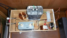
Tube amps have often filter chokes. These are allways 90 deg. to the xformer
E
Say you have the woofer xover coil of your 3way placed poorly next to the tweeter inductor. That 1% of crosscoupling of a 100Hz signal would be quite noticeable on a sustained 2kHz note. Sort of like IMF distortion
Maybe worth some experimentation?
Tube amps have often filter chokes. These are allways 90 deg. to the xformer
E
You have a valid point and that was exactly what my 0.3% number was all about, the cross-coupling of voltage with two coils spaced 2" apart, perimeter-to-perimeter. Still a 0.3% coupling of voltage is no more audible than a 0.6% change in inductance due to mutual inductance. Note that if you state 0.3% in dBs, it's -50 dB.
Paul
Paul
I do not believe the problem with poor placement of coils is in the change of inductance but in cross-coupling of frequencies
Say you have the woofer xover coil of your 3way placed poorly next to the tweeter inductor. That 1% of crosscoupling of a 100Hz signal would be quite noticeable on a sustained 2kHz note. Sort of like IMF distortion
Maybe worth some experimentation?
Tube amps have often filter chokes. These are allways 90 deg. to the xformer
E
- Status
- This old topic is closed. If you want to reopen this topic, contact a moderator using the "Report Post" button.
- Home
- Loudspeakers
- Multi-Way
- Help:Laying out inductors of crossover