New 3-way starting up! WWMTM
Hello!
3 years..ohh. actually many more ago I decided to make one pair of high end speakers. As a idea it wasnt not very bad at all, but in real world things are more difficult. I start reading this forum (with even more bad english, never learned in school), printing materials out, reading again, translating to have a clue what every specific technical term means. So step-by-step, day-by-day I soak new knowledges how one good speaker should work. As in this world there are many things you cant touch, you can hear them and if you have good measurement system, you can also see them. Thats did things for me also difficult and hard to understand. As I do love all woodworking job, I decided to put lot of attention to this part also. I think one side speaker should esthetically look nice and another side should sound also very well. I starter to even build my own garage (shop) where I can do all woodworking job. I built table saw, which makes pretty good job, bought all tools (router, biscuit machine etc). Ok, finally all were ready and installed to start difficult woodworking jobs. In the beginning I decided its goint to be 3-way, I know it is huge challange and we dont know, maybe I took too big piece, but keeping mind the learning curve, it is not waisting time. First I built actually boxes, they are stepped in purpose better time aligment. I do like narrow speakers, so woofers stay on side. I did lot of research choosing drivers, as money doesnt grow on threes, they are not the most expencive in world but they should be good to achieve my goal. I bought many midranges and tweeter drivers, but listening them a bit in free air and doing research I decided to keep:
4x Dayton RS225
4x Seas 15RLY
2x Peerless 810921
Next step was to buy measuring system to measure all kind of types values/indicators of drivers in my boxes. I am using ARTA/LIMP software for that. My thought was that I am going to measure first impedance of woofer (do get idea, does box works well and maybe need to tune vent or add filling material), after that I need measure response, freq range, step response etc. Model these in crossover software and built final crossover, listening etc..making changes and listening again. So lets go ahead and start with my first measurements of woofer at all.
Theoretically box is tuned to 32 Hz, it has inside V about 78L, side mounted woofers 2xRS225 parallel. My measurements show something like this:
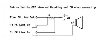
As a hardware i use this jig here:
AudioBlog: A simple loudspeaker measurement jig for ARTA
AudioBlog: A simple loudspeaker measurement jig for ARTA
reference resistor value 15,6 Ohm
and ARTA setup as here:
Starting measurement I get always warning from LIMP: maybe you need to exchange input channels. So, first question - are everything correct?
WOOFER test
I do have bass reflex system, but measurement curve (impedance) does not look very good. Did I do have somewhere something wrong?
MIDRANGE test
Looks good?
Hello!
3 years..ohh. actually many more ago I decided to make one pair of high end speakers. As a idea it wasnt not very bad at all, but in real world things are more difficult. I start reading this forum (with even more bad english, never learned in school), printing materials out, reading again, translating to have a clue what every specific technical term means. So step-by-step, day-by-day I soak new knowledges how one good speaker should work. As in this world there are many things you cant touch, you can hear them and if you have good measurement system, you can also see them. Thats did things for me also difficult and hard to understand. As I do love all woodworking job, I decided to put lot of attention to this part also. I think one side speaker should esthetically look nice and another side should sound also very well. I starter to even build my own garage (shop) where I can do all woodworking job. I built table saw, which makes pretty good job, bought all tools (router, biscuit machine etc). Ok, finally all were ready and installed to start difficult woodworking jobs. In the beginning I decided its goint to be 3-way, I know it is huge challange and we dont know, maybe I took too big piece, but keeping mind the learning curve, it is not waisting time. First I built actually boxes, they are stepped in purpose better time aligment. I do like narrow speakers, so woofers stay on side. I did lot of research choosing drivers, as money doesnt grow on threes, they are not the most expencive in world but they should be good to achieve my goal. I bought many midranges and tweeter drivers, but listening them a bit in free air and doing research I decided to keep:
4x Dayton RS225
4x Seas 15RLY
2x Peerless 810921
Next step was to buy measuring system to measure all kind of types values/indicators of drivers in my boxes. I am using ARTA/LIMP software for that. My thought was that I am going to measure first impedance of woofer (do get idea, does box works well and maybe need to tune vent or add filling material), after that I need measure response, freq range, step response etc. Model these in crossover software and built final crossover, listening etc..making changes and listening again. So lets go ahead and start with my first measurements of woofer at all.
Theoretically box is tuned to 32 Hz, it has inside V about 78L, side mounted woofers 2xRS225 parallel. My measurements show something like this:
As a hardware i use this jig here:
AudioBlog: A simple loudspeaker measurement jig for ARTA
AudioBlog: A simple loudspeaker measurement jig for ARTA
reference resistor value 15,6 Ohm
and ARTA setup as here:
An externally hosted image should be here but it was not working when we last tested it.
Starting measurement I get always warning from LIMP: maybe you need to exchange input channels. So, first question - are everything correct?
WOOFER test
I do have bass reflex system, but measurement curve (impedance) does not look very good. Did I do have somewhere something wrong?
An externally hosted image should be here but it was not working when we last tested it.
MIDRANGE test
Looks good?
An externally hosted image should be here but it was not working when we last tested it.
Last edited:
the curves look good, but the impedance values are too high...
have you calibrated your ARTA setup? , the addition of switch to your rig makes this easy
I find i get a better graph if I limit the low end to around the point where the low freq impedance hump begins.
Are you testing the drivers in free air (the usual method), or in the box?
have you calibrated your ARTA setup? , the addition of switch to your rig makes this easy
I find i get a better graph if I limit the low end to around the point where the low freq impedance hump begins.
Are you testing the drivers in free air (the usual method), or in the box?
Attachments
LIMP jig is switched ON, I think the same way that impedance is too high. I will need to read manual again how to calibrate LIMP setup. All I did just entered reference resistor valuein setup. I am testing woofer in box to get clue, how my box is working. PC-EMU0404-jig-speaker. No amp!
As it is vented system, I thought I should get totally different impedance curve: double peak and F3 between them.
Is that correct?
As it is vented system, I thought I should get totally different impedance curve: double peak and F3 between them.
Is that correct?
OK!
Have done again some research and got some experienced people advice. I did add amplifier to my measurement setup as it was necessary. Did calibrate LIMP and use reference resistor 15.6 oHm. So today played around again with my speaker project. I did a lot impedance measurements:
1) 2x RS225 Dayton parallelin box
2) RS 225 Dayton in free air
First of all I would like to share my results of 2xRS225 mounted in box, finally I got pretty ok results. As a box I use following physical parametes:
Vb=75 L
F3=31Hz
2xports diam 65mm, lenght 270mm
What do you think?
green=original setup
yellow=without ports (just checking does everything works well)
After that I measured TS parametes for 2 drivers in free air also:
Fs, 31.18 Hz
Re, 6.40 ohms[dc]
Le, 481.72 uH
L2, 67765.58 uH
R2, 17.43 ohms
Qt, 0.21
Qes, 0.24
Qms, 1.39
Mms, 19.02 grams
Rms, 2.674077 kg/s
Cms, 0.001370 m/N
Vas, 77.79 liters
Sd, 201.06 cm^2
Bl, 9.956219 Tm
ETA, 0.94 %
Lp(2.83V/1m), 92.82 dB
Here you can find manufacturer data:Dayton RS225S-8 8" Reference Shielded Woofer 8 295-366
So it looks like not very close. Qms fe 0,21 vs 0,53. Does that makes sence? If I am simulating those results with Unibox never get good graph tuning box to 31-33 Hz. As I already have built box, nothing can change.
ps! for ears bass sounds very good. From imp grapg it looks like port is also working.
Please all advices are welkome!
Have done again some research and got some experienced people advice. I did add amplifier to my measurement setup as it was necessary. Did calibrate LIMP and use reference resistor 15.6 oHm. So today played around again with my speaker project. I did a lot impedance measurements:
1) 2x RS225 Dayton parallelin box
2) RS 225 Dayton in free air
First of all I would like to share my results of 2xRS225 mounted in box, finally I got pretty ok results. As a box I use following physical parametes:
Vb=75 L
F3=31Hz
2xports diam 65mm, lenght 270mm
What do you think?
An externally hosted image should be here but it was not working when we last tested it.
green=original setup
yellow=without ports (just checking does everything works well)
After that I measured TS parametes for 2 drivers in free air also:
Fs, 31.18 Hz
Re, 6.40 ohms[dc]
Le, 481.72 uH
L2, 67765.58 uH
R2, 17.43 ohms
Qt, 0.21
Qes, 0.24
Qms, 1.39
Mms, 19.02 grams
Rms, 2.674077 kg/s
Cms, 0.001370 m/N
Vas, 77.79 liters
Sd, 201.06 cm^2
Bl, 9.956219 Tm
ETA, 0.94 %
Lp(2.83V/1m), 92.82 dB
Here you can find manufacturer data:Dayton RS225S-8 8" Reference Shielded Woofer 8 295-366
So it looks like not very close. Qms fe 0,21 vs 0,53. Does that makes sence? If I am simulating those results with Unibox never get good graph tuning box to 31-33 Hz. As I already have built box, nothing can change.
ps! for ears bass sounds very good. From imp grapg it looks like port is also working.
Please all advices are welkome!
Now looks everything good for impedance curve, after switched input channels and not getting any warning by LIMP. Here is my last measurements:
Today I played a bit bit with extra stuffing material. Just bought this:
Stuffing material is 8 mm thick. So right now I do have 2 layers of stuffing material (very light and soft sheet wadding (white material used in textile factory)+this more dense grey layer. Here you can find difference in imp curve also, after I added this gery material:
green=after
As you can see F3 went just a littlebit lower, approx 29-30Hz. So my question is, how can I verify bass output quality? Listening expression is very subjective and I cant notice any big difference before and after adding stuffing material. Bass output is enough deep for me right now, I have wired 2 drivers parallel to increase sensitivity compared midrange and tweet. As I will have 2x midrange (wired in series) I need definately L-pad for mid and tweet.
Can I measure somehow bass output, which is optimal for this enclosure? Please all opinions are welcome! Or my setup right now looks already good?
An externally hosted image should be here but it was not working when we last tested it.
Today I played a bit bit with extra stuffing material. Just bought this:
An externally hosted image should be here but it was not working when we last tested it.
An externally hosted image should be here but it was not working when we last tested it.
Stuffing material is 8 mm thick. So right now I do have 2 layers of stuffing material (very light and soft sheet wadding (white material used in textile factory)+this more dense grey layer. Here you can find difference in imp curve also, after I added this gery material:
An externally hosted image should be here but it was not working when we last tested it.
green=after
As you can see F3 went just a littlebit lower, approx 29-30Hz. So my question is, how can I verify bass output quality? Listening expression is very subjective and I cant notice any big difference before and after adding stuffing material. Bass output is enough deep for me right now, I have wired 2 drivers parallel to increase sensitivity compared midrange and tweet. As I will have 2x midrange (wired in series) I need definately L-pad for mid and tweet.
Can I measure somehow bass output, which is optimal for this enclosure? Please all opinions are welcome! Or my setup right now looks already good?
OK!
Step-by-step my project is moving along. I have done some work with speakers visual look, they were so time-consuming. I installed special wood rings for midrange section to fit drivers better. Then piano laquer these and sand-polish. It is very easy to cut trough, so this was not so funny job. Right now 95% is done, some ideas I still have.
Well, I played last weekend with LIMP and measure woofer section imp curve in different setup. So, I made 2 tests:
1) basic
2) longer port+added filler
Here is results:
My question is - how can I determine, which of these setup is better? I prefer Fs 27-30Hz. I think it is very hard to notice any difference by ear between these 2 setups. I like to make conclusion by measurement. Any ideas? Am I working towards right direction?
Step-by-step my project is moving along. I have done some work with speakers visual look, they were so time-consuming. I installed special wood rings for midrange section to fit drivers better. Then piano laquer these and sand-polish. It is very easy to cut trough, so this was not so funny job. Right now 95% is done, some ideas I still have.
Well, I played last weekend with LIMP and measure woofer section imp curve in different setup. So, I made 2 tests:
1) basic
2) longer port+added filler
Here is results:
An externally hosted image should be here but it was not working when we last tested it.
My question is - how can I determine, which of these setup is better? I prefer Fs 27-30Hz. I think it is very hard to notice any difference by ear between these 2 setups. I like to make conclusion by measurement. Any ideas? Am I working towards right direction?
The TS-parameters you measured would give a driver impedance of 43.5 ohm at 31.18 Hz. As the Dayton usually only has 24 ohm at Fs, there seems to be something wrong. Qms is ok, but Qes should be around 0.5.
It's impossible to determine from the impedance curves, which one of the two setups is better. But two vents of 65 x 270 mm are basically ok. Do the fine tuning later after having finished the crossover.
The impedance plot reveals an additional resonance at 110 Hz, typical for tower-shaped cabinets having a height around 1m. Designing the crossover will not be easy, but the drivers are fine and the sensitivities match. You may end with an excellent result!
OK!
I made speaker box based on RS225 manufacturer data.
Btw, why high (mine 20x45x145cm, slim) floorstander have some additional resonance around 100Hz? So this is the resonance of box?
jerome69-why do you prefer geern curve. This setup lower Fs and both imp peaks are close to same level. As I added some infill, 100Hz resonance also smoothened.
OK!
Btw, why high (mine 20x45x145cm, slim) floorstander have some additional resonance around 100Hz? So this is the resonance of box?
Yes, it's a standig wave at the inside of the box. Long and slim cabinets behave like as transmission line.
jerome69-why do you prefer geern curve. This setup lower Fs and both imp peaks are close to same level. As I added some infill, 100Hz resonance also smoothened.
That are the reasons
")
Hi,
You have a lot of flexibility with the bass alignment.
Sealed should give an around Bessel q=0.6 second order roll-off.
Tuning 78L to 32Hz gives the classic maximally flat Butterworth.
Tuning to 22Hz gives a very nice overdamped roll off that is effectively
2nd order down to 20Hz, with a very good -10dB point of 22Hz.
(The best / optimum -10dB point is reached by the 22Hz tuning,
with room gain this should reflect the lowest practical limit.)
Basically you can tune to anywhere between 22Hz and 32Hz to taste.
Low tunings will give deep no fuss extended bass similar to sealed
but but steadily increasing low output over sealed (+4dB @ 20Hz).
rgds, sreten.
Closing off one port will detune by 0.7, as will doubling port lengths.
Last edited:
- Status
- This old topic is closed. If you want to reopen this topic, contact a moderator using the "Report Post" button.
- Home
- Loudspeakers
- Multi-Way
- My first 3-way + measurements