I'll upload in a few hours a better photo of the jig so you can see. The limitation of the jig is the minimum circle diameter you can do. The centerpin is fixed, you move the router nearer or further away from the centerpin.
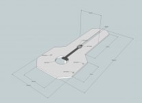
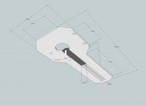
I just finished drawing a new jig. See files attached of the new design. Though not original, it's inspired on existing design. The benefit of this design is that you can move to center pin very close to the router bit. The router itself is fixed to the jig. After setting the radius the sliding part is fixed with a plate and wing-nut (not really drawn). You can also flip the slinding part 180 degrees to allow for large radius cuts.
I just finished drawing a new jig. See files attached of the new design. Though not original, it's inspired on existing design. The benefit of this design is that you can move to center pin very close to the router bit. The router itself is fixed to the jig. After setting the radius the sliding part is fixed with a plate and wing-nut (not really drawn). You can also flip the slinding part 180 degrees to allow for large radius cuts.
Attachments
Last edited:
Is that drawn with sketchup? You are very good with 3D.
I am using the ROUTER BUDDY CIRCLE JIG and it works well enough but the trouble I have is that in setting the size you have to turn it over and there are no markings so one must always do a test cut before actually cutting, so it is very inconvenient to adjust.
If you could design a jig that could be accurately adjusted in-place, that would be something!")
I am using the ROUTER BUDDY CIRCLE JIG and it works well enough but the trouble I have is that in setting the size you have to turn it over and there are no markings so one must always do a test cut before actually cutting, so it is very inconvenient to adjust.
If you could design a jig that could be accurately adjusted in-place, that would be something!
Yup, Sketchup.
That "router buddy circle jig" does not look very sturdy, just a "wacky" strip of metal going to the center pin....Yes I see, setting that for the correct dimension might be cumbersome.
To add a scale to the jig I use could be done but as soon as you use different size cutting bit's you have to compensate for that when setting the radius with use of the scale.
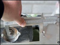
I just use a caliper, I'll show in a pic or (youtube movie) later today how I do that with this jig. very straightformward.
That "router buddy circle jig" does not look very sturdy, just a "wacky" strip of metal going to the center pin....Yes I see, setting that for the correct dimension might be cumbersome.
To add a scale to the jig I use could be done but as soon as you use different size cutting bit's you have to compensate for that when setting the radius with use of the scale.
I just use a caliper, I'll show in a pic or (youtube movie) later today how I do that with this jig. very straightformward.
It is actually sturdier than it looks, just not very user friendly. I use a caliper but that seems to always only get me within a few mm when I really want to be within 1mm.
I use this bit: 1/4 in. x 1 in. Carbide Up Spiral Router Bit-DR75102 at The Home Depot
Perhaps you could add a sliding rule on top of your jig that could be adjusted to compensate for bit width within a cm or so and clamped with a screw. One side would be for when the pin is in one way and the other for when it is flipped around.
Ah, I see, those kind of bits are probably a bit difficult to measure and set with a caliper.
I use these kind of router bits: http://www.jvl-europe.nl/img/021203CB-2.jpg it's basically two chisels fixed to a body, they can be grinded a few times to sharpen.
When I set the radius and make a test cut just to verify I was until now always exact on the money.
I use these kind of router bits: http://www.jvl-europe.nl/img/021203CB-2.jpg it's basically two chisels fixed to a body, they can be grinded a few times to sharpen.
When I set the radius and make a test cut just to verify I was until now always exact on the money.
I was thinking the problem was more that I was trying to estimate the center of the pin, which is rather narrow. My eyes aren't so good for that anymore. The other end just goes to the outside of the flute.Ah, I see, those kind of bits are probably a bit difficult to measure and set with a caliper.
I use these kind of router bits: http://www.jvl-europe.nl/img/021203CB-2.jpg it's basically two chisels fixed to a body, they can be grinded a few times to sharpen.
When I set the radius and make a test cut just to verify I was until now always exact on the money.
Truth be told I'm not the most skilled woodworker either.
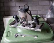
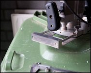
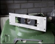
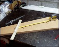
Here are some photo's of the current jig.
It's a sheet of metal with a cutout for the cutter. At the end are to solid blocks of metal which hold 2 rods, 1 on each side. Many european routers have (at varying dimensions) holes in the base to put such rods through. At one of the rods-ends a thread it cut (and in the block), on the otherside you can screw/unscrew the rods with a screwdriver. The routerbase has several wingnuts to tighten the base to the rods.
To setup the correct radius I turn the cutter to its horizontal position which will become the outside of the cut. I set the caliper to the desired size and add 3 mm (as the center is 6mm) to compensate for the fact that I include the center in my measurement. This to avoid to have to estimate/guess the what the center of the center is. This is also, like you mentioned, the reason you did not get it spot on at the first attempt.
The double check I have setup the jig okay I make two small cuts opposite of the center hole in some scrap wood.
Key is that the jig is rocksolid.
Attachments
Last edited:
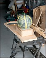
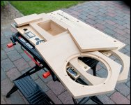
I constructed the mid-chamber. Used a concrete pumpkin to put some pressure on the glue (not enough clamps for both). I opened the mid-chamber from the front using the router.
The baffle consists of 2 sheets of MDF, I cut the front sheet in 3 parts, the part covering the mid-chamber will be bolted on so I can reach it always from the front. This choice was also driven by the fact how the 10F will be mounted on the front sheet and the fact I can't access the chamber via the driver hole (and if it would have been very tiny).
The baffle consists of 2 sheets of MDF, I cut the front sheet in 3 parts, the part covering the mid-chamber will be bolted on so I can reach it always from the front. This choice was also driven by the fact how the 10F will be mounted on the front sheet and the fact I can't access the chamber via the driver hole (and if it would have been very tiny).
Attachments
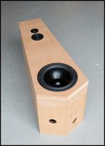
Started to paint the primer on. Filled and sanded down one time, 1 or 2 coats and filling needed to get it smooth as a......
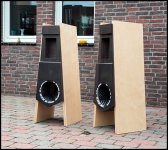
To get an idea how it will be I put the birch plywood panels against the cabinet and with photoshop I made the gray primer darker. It should look now very similar to the final product.
To get an idea how it will be I put the birch plywood panels against the cabinet and with photoshop I made the gray primer darker. It should look now very similar to the final product.
Attachments
Small update.
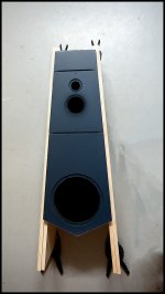
After extensive sanding, priming etc I left the cabinets last week at a professional paintshop. Expect a call from them any day now that I can come to pick them up again. They'll get a high-gloss, pearl, car paint finish.
I tried to paint them myself but too much dust to make a success of that attempt.
- Status
- This old topic is closed. If you want to reopen this topic, contact a moderator using the "Report Post" button.
- Home
- Loudspeakers
- Multi-Way
- Loudspeaker Build Thread