If anyone wants to make their own Paralines, I've written a spreadsheet that will calculate most of the dimensions for you.
The spreadsheet is easy to use. Simply plug in three variables:
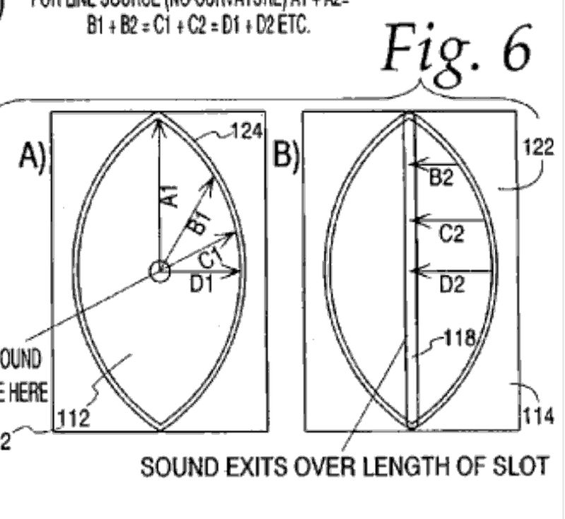
That's it! The calculator figures everything else out. It will tell you how tall the Paraline should be, how wide it should be, and most importantly, the length of A1 and D1. (Width and height of the Paraline path.)
One thing that's lacking is B1 and C1. For my projects, I'll likely just sketch these in an 'eye' shape, like the 'real' Paraline.
The size of the Paraline mouth is calculated, based on the area of the 'ring' that the Paraline is bending. You'll notice that the mouth gets bigger as the Paraline gets bigger, just as we'd expect. The mouth size is based on the assumption that the Paraline is 1/4" in height inside of the line. (0.635cm)
If you tinker with the spreadsheet, you'll notice that as the Paraline coverage angle gets wider, it gets skinnier and skinnier and skinnier.
For instance, the VTC Paraline has a narrow coverage angle, something like 10-20 degrees. Due to that, it's width is basically half of it's height. But as you widen the coverage angle, the 'center' of the Paraline has to lead it's edges. Due to that, the Paraline gets skinnier and skinnier and skinnier as the coverage gets wider. If you're doing car audio or home theater, you might be able to juggle that variable to get a tall skinny speaker, or a short one.
I made the spreadsheet in Google Docs; for some reason the graph disappeared when I converted it to Excel. On lines 23-26 there are the coordinates of the most important points in the Paraline. Basically 0,0 is at the center of the Paraline, and points 1,2,3,4 are 12 o clock, 3 o clock, six o clock and 9 o clock on the Paraline.
If the spreadsheet doesn't make any sense, here are some resources to study.
#1 - the Paraline patent: Patent US20090323997 - Horn-loaded acoustic line source - Google Patents
#2 - Danley's comments on diyaudio, where he talks about how you can bend the wavefront. This is important, because it allows us to make the wavefront larger or smaller. For instance, if you want to get blasted in the face, you can select a coverage angle of 0.1 degrees. In that configuration, the Paraline wavefront at your face will basically be the same as at the throat. So you'll get a full face full o' treble. (Yes, that's why this thread is named "Sunshine." It's an homage to the radical sci-fi flick "Sunshine.")
More than likely, you DON'T want to get sunburned by your compression driver, so you'll likely choose an angle with wider coverage. The Paraline can bend the wavefront, so you can 'dial in' whatever angle you want. Well, up to 180 degrees actually. I haven't seen any Paralines that bend the wavefront aggressively, so I don't know how the Paraline will behave if you go for wide coverage. But theoretically, you can go to 180. My spreadsheet goes to 180.
Here's the data from Danley:
http://www.diyaudio.com/forums/multi-way/133745-i-dont-understand-6.html#post2925569
The spreadsheet is easy to use. Simply plug in three variables:
- The height of the Paraline. The commercial Paraline used by VTC is about 20cm tall, so that's what's in my spreadsheet. Danley has mentioned that there are Paralines that are 180cm tall.
- The distance to the listener. Basically as you get further and further from the loudspeaker you likely want to decrease the coverage angle of the Paraline. (This applies to all horns really.)
- "Desired Image Height" Basically my spreadsheet is set up so that you pick an image height, and it calculates everything based on that. This is a bit backwards; a lot of people look at these things in terms of degrees. But personally, I'm more focused on how big of an audience I need to cover. For instance, the default settings on my calculator are set for a width of just 170cm, or about 5.5'.
That's it! The calculator figures everything else out. It will tell you how tall the Paraline should be, how wide it should be, and most importantly, the length of A1 and D1. (Width and height of the Paraline path.)
One thing that's lacking is B1 and C1. For my projects, I'll likely just sketch these in an 'eye' shape, like the 'real' Paraline.
The size of the Paraline mouth is calculated, based on the area of the 'ring' that the Paraline is bending. You'll notice that the mouth gets bigger as the Paraline gets bigger, just as we'd expect. The mouth size is based on the assumption that the Paraline is 1/4" in height inside of the line. (0.635cm)
If you tinker with the spreadsheet, you'll notice that as the Paraline coverage angle gets wider, it gets skinnier and skinnier and skinnier.
For instance, the VTC Paraline has a narrow coverage angle, something like 10-20 degrees. Due to that, it's width is basically half of it's height. But as you widen the coverage angle, the 'center' of the Paraline has to lead it's edges. Due to that, the Paraline gets skinnier and skinnier and skinnier as the coverage gets wider. If you're doing car audio or home theater, you might be able to juggle that variable to get a tall skinny speaker, or a short one.
I made the spreadsheet in Google Docs; for some reason the graph disappeared when I converted it to Excel. On lines 23-26 there are the coordinates of the most important points in the Paraline. Basically 0,0 is at the center of the Paraline, and points 1,2,3,4 are 12 o clock, 3 o clock, six o clock and 9 o clock on the Paraline.
If the spreadsheet doesn't make any sense, here are some resources to study.
#1 - the Paraline patent: Patent US20090323997 - Horn-loaded acoustic line source - Google Patents
#2 - Danley's comments on diyaudio, where he talks about how you can bend the wavefront. This is important, because it allows us to make the wavefront larger or smaller. For instance, if you want to get blasted in the face, you can select a coverage angle of 0.1 degrees. In that configuration, the Paraline wavefront at your face will basically be the same as at the throat. So you'll get a full face full o' treble. (Yes, that's why this thread is named "Sunshine." It's an homage to the radical sci-fi flick "Sunshine.")
More than likely, you DON'T want to get sunburned by your compression driver, so you'll likely choose an angle with wider coverage. The Paraline can bend the wavefront, so you can 'dial in' whatever angle you want. Well, up to 180 degrees actually. I haven't seen any Paralines that bend the wavefront aggressively, so I don't know how the Paraline will behave if you go for wide coverage. But theoretically, you can go to 180. My spreadsheet goes to 180.
Here's the data from Danley:
http://www.diyaudio.com/forums/multi-way/133745-i-dont-understand-6.html#post2925569
Attachments
Last edited:
Paraline stacking vs vertical dispersion
Hi Patrick,
I'm new to the forum and have followed this thread the past weeks. I am curious to know what happens to the vertical dispersion when you stack up(vertically) multiple paraline elements? Does the vertical beamwidth narrow as it does in entire operational bandwidth region or it narrows differently relative to the frequency bands concerned? And by what factor?
It intrigued me to think about above as unlike in a conventional horn where the relative spl at horn ends is -6db, I understand in paraline lens the same is -3db.
Will much appreciate any informations on above.
Thanks and regards,
Shekhar
Shekhar,Hi Patrick,
I'm new to the forum and have followed this thread the past weeks. I am curious to know what happens to the vertical dispersion when you stack up(vertically) multiple paraline elements? Does the vertical beamwidth narrow as it does in entire operational bandwidth region or it narrows differently relative to the frequency bands concerned? And by what factor?
It intrigued me to think about above as unlike in a conventional horn where the relative spl at horn ends is -6db, I understand in paraline lens the same is -3db.
Will much appreciate any informations on above.
Thanks and regards,
Shekhar
The very high frequencies are well controlled by the Paraline, in a equal path length version you basically are hearing sum of all the drivers when at a long distance from the line.
Usually some arc or "J" shape is needed to cover the audience, which effectively means in the VHF each unit is covering only a specific area.
At lower frequencies where the wavelength approaches the horn height and looses any pattern control, there is far more mutual coupling, extending upwards of 4000 Hz.
The longer the line, the more midrange attenuation (or HF boost) is needed to maintain flat response.
In my Paraline line array, when looking at the difference between one unit and 5 units tall the difference is around 10 dB of mid attenuation needed.
I have used a converging pattern at times, and actually had more HF at 100 meters than near the stack, which is good if people are there to hear (and absorb) the HF, but bad if the back of the room is empty and you get to hear the HF reflecting off the back wall...
Art Welter
Thanks for your reply Patrick,
Now I'm thinking if we create a straight vertical stack (4X) of four praline elements where each paraline element has a 20deg vertical dispersion, what happens to the net vertical dispersion of this stack? Does it get reduced to 5deg (-6) db points or the reduction is of a different scale. Correct me if i'm wrong but as I understand, for every doubling of sources the dispersion in the plane of coupling reduces to half(provided the sources are 1/4th or less wavelength apart)
On the other hand if a single praline element with 15deg vertical dispersion is coupled to a straight conic horn to provide full loading and pattern control in both vertical and horizontal planes. And four of these are stacked in the vertical plane, does the summation still remain frequency dependent or its broadband for the entire bandwidth of the element (given that each element has full loading to its low cut off frequency)? Will the summation of these fully loaded paraline horns still follow the above rule of reducing dispersion with increasing elements in a straight line in the given plane?
I was going through the spreadsheet you have posted and was observing the dispersion angle change with different parameter changes, is this figure the same as the vertical dispersion angle of a single paraline?
Shekhar
Shekhar,
Combining Paraline HF drivers that have overlapping HF patterns will cause comb filtering which will vary with frequency and distance, the reason VTC (and I) make a very tight HF pattern Paraline for our line arrays.
The comb filtering can actually lessen HF output in the far field over a single unit.
Danley's use of Paralines are in a single horn, if multiple units were vertically arrayed, they would need to be arranged as part of a sphere to avoid comb filtering.
I have not looked at Patrick's spreadsheet.
At any rate, a spreadsheet probably would not be able to include enough variables to compute dispersion patterns for more than one Paraline at one frequency at a time.
Art Welter
Last edited:

Dear Art,
Thanks for your valuable inputs and advise. Sure I understand about the comb filtering in case of multiple cabinets used together but if we keep the maximum/minimum phase difference between the leading/trailing edge of the exit waves in multiple paraline elements (in a straight line array) to less than 45 degrees at the highest usable frequency. Lets say at 13.5 Khz, then the maximum loss due to comb filtering at this highest frequency will be under 1 db and it will get progressively lesser as we move down the frequency scale. Assuming just two possibilities of either a straight line array or a curved array with close to Zero overlap between any two adjusent cabinets, this way we manage to avoid almost all of comb filtering effects upto the frequency where each individual cabinet exibits complete pattern control.
Or am I missing out on something in between here?
Shekhar
Correct, with the "almost" part emphasized, the reason DSL still has no line array cabinets in their line.Assuming just two possibilities of either a straight line array or a curved array with close to Zero overlap between any two adjusent cabinets, this way we manage to avoid almost all of comb filtering effects upto the frequency where each individual cabinet exibits complete pattern control.
Shekhar
Hi guys,
I'm trying to understand how the Danley GH60 works. This thread has been very helpful.
I think I understand how the Shaded Amplitude Lens works.
I get the basic idea behind the Paraline as well, I think. Is it correct that the amplitude of the wave front that exits a Paraline (with two narrow exit slots) is lower in the centre (between the two slots) than at the centre of the individual slots? I'm trying to figure out what the advantage is of putting a Paraline behind the Shaded Amplitude Lens; so far I seem to be neglecting something I think? Or is the Paraline simply a way to combine multiple compression drivers?
The Paraline is simply a novel way to fold a radial horn. It's a horn that radiates in 360 degrees, with a reflector in the middle of it that bends the wavefront 180 degrees.
The main advantages of a Paraline, as I see it, is that you can get a very very very narrow vertical directivity. For instance, you can get a vertical directivity of ten degrees or less. And it's this narrow vertical directivity that allows you to stack the compression drivers on top of each other. Basically they don't interfere with each other for the most part, because the vertical directivity is so narrow.
The amplitude shading of a Paraline is simply a bonus, and it reduces the interference between compression drivers that are stacked on top of each other.
Another weird aspect of the Paraline, that Art Welter noted, is that you can basically eliminate 50% of the horn, because the directivity is so narrow the top and the bottom of the horn basically don't need to be there.
That has some interesting advantages if you want to put a Paraline into a corner, because you can use the walls to form the horn.
A Paraline uses a single exit slot, multiple driver Paralines have the single slot stacked vertically.Hi guys,
I'm trying to understand how the Danley GH60 works. This thread has been very helpful.
I think I understand how the Shaded Amplitude Lens works.
I get the basic idea behind the Paraline as well, I think. Is it correct that the amplitude of the wave front that exits a Paraline (with two narrow exit slots) is lower in the centre (between the two slots) than at the centre of the individual slots? I'm trying to figure out what the advantage is of putting a Paraline behind the Shaded Amplitude Lens; so far I seem to be neglecting something I think? Or is the Paraline simply a way to combine multiple compression drivers?
The amplitude of the wave front that exits a Paraline is equal from top to bottom, which is why it works well in both a line array or a single horn such as the GH60.
The Shaded Amplitude Lens redirects a small portion of the output of multiple driver Paralines downward at a reduced level to compensate for the inverse distance law.
It appears DSL has abandoned this approach in the larger scale Biblical named units and may be using "astigmatic" Paralines instead to provide a controlled variable vertical dispersion, reducing the parts count and build difficulty and reducing diffraction effects.
Art
Posting the same question in three threads is bad form.hi guys . just wondering , since paraline loading is very effecient in hf drivers.
>>>> can paraline loading be used in unity horn or synergy horn tweeters like in danleys gh60 .
Paraline loading is no more efficient than a conical horn.
The purpose of a Paraline is to reduce vertical dispersion to only a few degrees without requiring a long throat, not what one normally wants in a Unity/Synergy horn.
Paralines are useful for combining HF driver output, a home use Unity/Synergy only needs one HF driver, a Paraline increases the build complexity, and makes the frequency response more ragged.
I made some animations using Xara and Hornresp to illustrate how the lens in the Beolab works. Same idea applied to the Paraline. It's interesting to watch the spherical wave get "bent" into a flat wave. But you can also see that the process is not perfect, and that's probably why the high frequency response of both devices has narrow peaks and dips.
Is that audible? It's open to debate.
More musings here:
bang and olufsen tweeter lens idea - Car Audio | DiyMobileAudio.com | Car Stereo Forum
I may not have made it clear, but both the Paraline and the Beolab lens use virtually the same curve and work virtually the same way. Both take a point source with wide directivity and turn it into a line source with narrow vertical directivity.
This is a Paraline, with tweeter in the center
This is a Beolab, with a tweeter in the center
Here's both, overlaid. See how it's the same curve?
This is a Paraline, with tweeter in the center
An externally hosted image should be here but it was not working when we last tested it.
This is a Beolab, with a tweeter in the center
An externally hosted image should be here but it was not working when we last tested it.
Here's both, overlaid. See how it's the same curve?
Nice for a super tweeter.
Probably would be better with a parabolic curve with source at the focal point.
Here is a radical idea - why not use a contoured waveguide over the source to create the desired wavefront without any reflections or diffraction. That might work well.
WAIT! I just remembered, it does work well. Who'd have guessed!

Direct sound radiation seems to always provide the best reproduction, reflection always result in a maze of interacting waves which kind of fuzzies the sound, works well if you consider other considerations such as looks. It is only a matter how to sacrifice the lease to get the looks you want and the cost involved. The simplerer and cleaner the shape contour, the more sound you preserve.
I tried the concept.
I tried the concept.
- Status
- This old topic is closed. If you want to reopen this topic, contact a moderator using the "Report Post" button.
- Home
- Loudspeakers
- Multi-Way
- ~ Sunshine ~