Hi All,
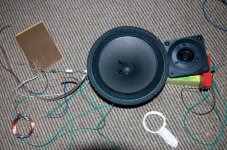
I have picked up some cheap drivers last weekend and am wanting to design a cabinet for them. These are just a little fun side project, nothing too serious.
I wired the drivers in parallel and they sounded ok straight on, as both the tweeter and woofer are around the same sensitivity so neither one overpowered the other.
I am not sure what crossover frequency I should aim for and what cabinet type I should go for. My first set of speakers are actively crossed 3-ways so I am new to passive crossovers.
I would say my crossover budget is around $50
I was thinking about building a 60L vented enclosure. I am unsure on the best dimensions for this and where on cabinet I should place the drivers, I was thinking that the tweeter and driver should be as close to each other as possible?
16mm MDF with lots of bracing should be fine for construction?
http://www.surplustronics.co.nz/shop/product-SP2202.html
http://www.surplustronics.co.nz/shop/product-902.376.html
What information I could find on the driver:
Re - 7
Fs - 46
Qms - 2.82
Qes - 0.63
Qts - 0.52
Sd(CM2) - 211
Vas(L) - 33.5
Cms(uM/N) - 531
Mms(g) - 22
Rms B x L - 8.5
SPL_1W/1m2 - 89
Prms(W) - 60
Pmax(W) - 120
Xmax - 1.5
Any ideas and suggestions would be much appreciated.
Cheers,
Jake
60L tuned to the mid 30s is about right, yes the tweeter should be close as possible to the woofer. Dimensions - Keep the tweeter about ear height, & internal volume constant, then make it any shape you like - wider is better for low baffle step (my preference), narrower is purportedly better for imaging.
Without a freq response graph for the woofer, it's hard to choose a crossover freq. I'd use the recommended 3KHz for the tweeter as a starting point. Because the woofer is a dual cone, it's response is probably pretty ragged up high, go for a 2nd order crossover to start with.... Then you may need to modify it to add some baffle step correction if you find you want more mids & bass.
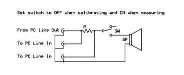
To choose crossover components accurately, you'll need impedance plots for the drivers: Download ARTA: ARTA Your Page Title, Make this simple jig: ARTA Jig - AudioBlog: A simple loudspeaker measurement jig for ARTA
Without a freq response graph for the woofer, it's hard to choose a crossover freq. I'd use the recommended 3KHz for the tweeter as a starting point. Because the woofer is a dual cone, it's response is probably pretty ragged up high, go for a 2nd order crossover to start with.... Then you may need to modify it to add some baffle step correction if you find you want more mids & bass.
To choose crossover components accurately, you'll need impedance plots for the drivers: Download ARTA: ARTA Your Page Title, Make this simple jig: ARTA Jig - AudioBlog: A simple loudspeaker measurement jig for ARTA
Attachments
Hi Jake,
Since I don't think there are any response or impedance charts available for the drivers (unless you can measure them?), you'll just be shooting for "functional" and nothing special here (I have no problem with this personally, especially if it's cheap. The chance to build something is always a good thing).
In my experience, the best results in these "shooting in the dark" crossover builds will come from a pretty simple 4 component x-over. An inductor on the woofer, cap on the tweeter, and a zobel circuit on the woofer. There's more room for error in a shallow slope build. Considering the fact that the woofer only has 1.5mm of Xmax, I highly doubt you'll run into power handling problems on the tweeter before running out of Xmax on the woofer even with the gentle single order slopes.
Use a crossover component calculator to come up with the values. 3K would be a safe bet, but I'd be tempted to push my luck with lower.
")
Hi Jake,
Since I don't think there are any response or impedance charts available for the drivers (unless you can measure them?), you'll just be shooting for "functional" and nothing special here (I have no problem with this personally, especially if it's cheap. The chance to build something is always a good thing).
In my experience, the best results in these "shooting in the dark" crossover builds will come from a pretty simple 4 component x-over. An inductor on the woofer, cap on the tweeter, and a zobel circuit on the woofer. There's more room for error in a shallow slope build. Considering the fact that the woofer only has 1.5mm of Xmax, I highly doubt you'll run into power handling problems on the tweeter before running out of Xmax on the woofer even with the gentle single order slopes.
Use a crossover component calculator to come up with the values. 3K would be a safe bet, but I'd be tempted to push my luck with lower.
Cheers, I hope to get the best results possible from the drivers. They will be powered by ~15w amps and are unlikely to ever experience more than 60W.
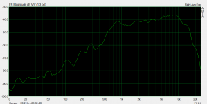
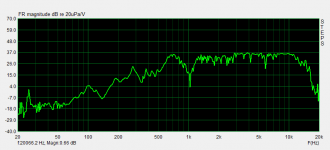
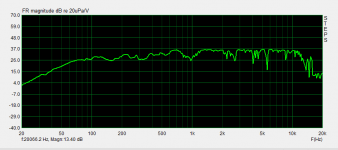
I will have a go at getting some frequency response graphs up - hopefully my mic will not sway the results too much.
Hi, some random thought.
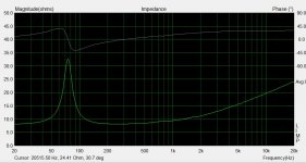
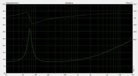
I assume you ran the impedance test in free air. If yes, it appears that the woofer has an Fs of 75 Hz instead of 46 Hz. Maybe you should input some 20-40 Hz tone for some hours to the woofer and re-run the test. And try also to calculate the full set of T/S parameters with arta. If the specs are way off to the real ones, you can't calculate a good box.
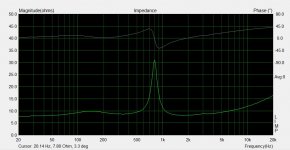
Second, the tweeter. It has a hard impedance peak at 800 Hz, meaning it probably doesn't have ferrofluid. Without good measuring equipment (more on that later), you should stay away from Fs and use at least a 2nd order electrical crossover on the tweeter. 3K Hz could be a good starting point. You could use a lower crossover point but you should tame the impedance peak, because if not it will appear also in the frequency response plot, and you will also stress the tweeter.
About the mic: what kind of mic is? Are you reasonably sure it has a flat response over a good range of frequencies (IMHO at least 100 Hz - 10KHz)? If not do you know its difference from flatness (you could input that into arta)?
If you don't know the response of the mic you can't use data collected through it for modeling a speaker.
About the frequency response graphs: what is the measurement environment? I mean did you ran the tests in free air or in a box or in an infinite baffle? It is difficult to draw some conclusions without this info.
And also you should gate the measure, because if not you are measuring also the room, and not only the drivers (and every time you move the drivers in the room you will have different data).
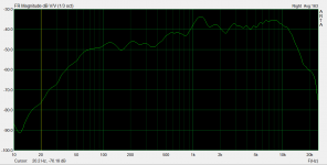
For now I'm ignoring the 10 dB difference between 300 Hz and > 1 KHz on the woofer.
Last. When you have reliable data for impedance and frequency response you can use some sw to model a crossover. For a good and free set of software see here: FRD Consortium tools guide
Ralf
I assume you ran the impedance test in free air. If yes, it appears that the woofer has an Fs of 75 Hz instead of 46 Hz. Maybe you should input some 20-40 Hz tone for some hours to the woofer and re-run the test. And try also to calculate the full set of T/S parameters with arta. If the specs are way off to the real ones, you can't calculate a good box.
Second, the tweeter. It has a hard impedance peak at 800 Hz, meaning it probably doesn't have ferrofluid. Without good measuring equipment (more on that later), you should stay away from Fs and use at least a 2nd order electrical crossover on the tweeter. 3K Hz could be a good starting point. You could use a lower crossover point but you should tame the impedance peak, because if not it will appear also in the frequency response plot, and you will also stress the tweeter.
About the mic: what kind of mic is? Are you reasonably sure it has a flat response over a good range of frequencies (IMHO at least 100 Hz - 10KHz)? If not do you know its difference from flatness (you could input that into arta)?
If you don't know the response of the mic you can't use data collected through it for modeling a speaker.
About the frequency response graphs: what is the measurement environment? I mean did you ran the tests in free air or in a box or in an infinite baffle? It is difficult to draw some conclusions without this info.
And also you should gate the measure, because if not you are measuring also the room, and not only the drivers (and every time you move the drivers in the room you will have different data).
For now I'm ignoring the 10 dB difference between 300 Hz and > 1 KHz on the woofer.
Last. When you have reliable data for impedance and frequency response you can use some sw to model a crossover. For a good and free set of software see here: FRD Consortium tools guide
Ralf
Hi Ralf,
Thanks for the advice!
I did run the impedance test in free air, I will give the woofer some low frequency work tonight for a few hours and re-run the test.
The mic is a small cheap one from a headset - not the best I know but it is all that I had at the time, I will see if I can find another to use. The steps test gave far better results but it looks like the attachments dropped off. I will post these up again tonight.
I am measuring in a closed wardrome to try and eliminate noise from my room, the mic and drivers are 300mm apart.
Last edited:
Thanks,
Should I remove the wizzer/attempt the 99c trick before measurement?
I have picked up a better microphone and will try and set up the test again with proper calibration this weekend.
Are their any problems with shallow cabenets? I was thinking building this one 400mm wide and 200mm deep and choose the hight to give approriate litreage ~800mm for 60L.
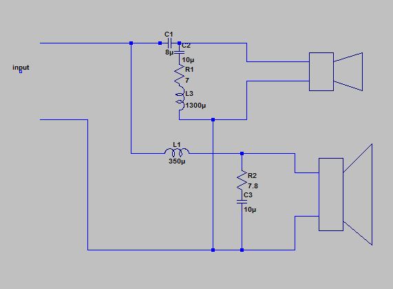
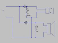
Just did a quick open air test with the below cross over, sounds decent - not at all disappointing.
I am using back to electro's and some big wima's for the moment. Will ceramic caps in parallel be a suitable trade-off for electro's?

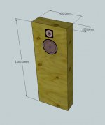
I have also picked up some 15mm ply, this has all been cut to size. External dimensions will be 1200x450x155.
Any idea's on driver placement?

I am using back to electro's and some big wima's for the moment. Will ceramic caps in parallel be a suitable trade-off for electro's?
I have also picked up some 15mm ply, this has all been cut to size. External dimensions will be 1200x450x155.
Any idea's on driver placement?
Attachments
Last edited:
Hi
I've seen you've decided to have a tall and thin tower.
It helps you to get a first result: to have the center of the tweeter just at the height of the listener.
So, seat down on your armchair and take the point of reference on the baffle.
Then, put the woofer just down the tweeter, closer than possible.
To reduce diffraction effects, tweeter can be put not exactly in the center of the baffle, but near one edge. Of course, a box has the tweeter near its left edge, the other near the right one.
Woofer shall be put exactly in the center.
I will post a sketch.
Hi
I've seen you've decided to have a tall and thin tower.
It helps you to get a first result: to have the center of the tweeter just at the height of the listener.
So, seat down on your armchair and take the point of reference on the baffle.
Then, put the woofer just down the tweeter, closer than possible.
To reduce diffraction effects, tweeter can be put not exactly in the center of the baffle, but near one edge. Of course, a box has the tweeter near its left edge, the other near the right one.
Woofer shall be put exactly in the center.
I will post a sketch.
Cheers slovnaft,
The sketch has not come through but I think I have got the idea.
I will mark out the baffle tonight.
Last edited:
Skech
Strange... I can see it.
Anyway, this is the concept:
where the center of the tweeter is at the height of your ears, when listening.
Cheers slovnaft,
The sketch has not come through but I think I have got the idea.
I will mark out the baffle tonight.
Strange... I can see it.
Anyway, this is the concept:
An externally hosted image should be here but it was not working when we last tested it.
where the center of the tweeter is at the height of your ears, when listening.
- Status
- This old topic is closed. If you want to reopen this topic, contact a moderator using the "Report Post" button.
- Home
- Loudspeakers
- Multi-Way
- Cheap 2-way Speakers - Design advice