I have a pair of speakers with the 3 way system broken. I bought woofer, mid, and tweeter to repair them.
Woofer: MHB Subwoofer 200 mm 8 Ohm

Mid: Goldwood GM-35 5.25" Midrange + 6.8µF capacitor (Filter)


Tweeter: Sound Lab L062E 10cm + 2.2µF capacitor (Filter)
Specs: 40W RMS/70 W Max, 1500-20000Hz, 92dB, 8 ohm.

I will use this capacitors if its a good way or cheap way to avoid the installation of a 3 way crossover (but i want know the best for my speakers)

¿Filter with capactiors or crossover?
Speakers without tweeter

Spakers connection (Parallel)

Thanks")
Woofer: MHB Subwoofer 200 mm 8 Ohm
- Specs: paper cone, 100 W Max, 90dB, 45-9000Hz, 8 ohms.
Mid: Goldwood GM-35 5.25" Midrange + 6.8µF capacitor (Filter)
- Specs: Paper cone, 3 oz. magnet, .75" KAPTON voice coil, 40 watts/RMS, 97 dB, 600-15,000 Hz, 8 ohms.
Tweeter: Sound Lab L062E 10cm + 2.2µF capacitor (Filter)
Specs: 40W RMS/70 W Max, 1500-20000Hz, 92dB, 8 ohm.
I will use this capacitors if its a good way or cheap way to avoid the installation of a 3 way crossover (but i want know the best for my speakers)
¿Filter with capactiors or crossover?
Speakers without tweeter
Spakers connection (Parallel)
Thanks
re:'its a good way or cheap way ' - it's a cheap way, but so is the quality of those speakers.
The first problem you need to deal with is the mid is 7dB louder than the woofer, you'll need to add an L-pad to match them : L pad calculator - attenuation dB damping impedance decibel loudspeaker speaker voltage divider - sengpielaudio Sengpiel Berlin
You will probably have to add an L- pad to the tweeter as well
re:'its a good way or cheap way ' - it's a cheap way, but so is the quality of those speakers.
The first problem you need to deal with is the mid is 7dB louder than the woofer, you'll need to add an L-pad to match them : L pad calculator - attenuation dB damping impedance decibel loudspeaker speaker voltage divider - sengpielaudio Sengpiel Berlin
You will probably have to add an L- pad to the tweeter as well
With L-Pad i will get flat frequency response ¿truth?
I just looked those units up. The tweeter is 92dB, the midrange 90dB and the woofer 90dB. Close enough to give them a go, I reckon. Shouldn't knock a 2.2 uF capacitor on a tweeter. I ran that for years on some speakers, but a 3R 5W series/20R 10W shunt in wirewound resistors after the capacitor would do no harm to attenuate the tweeter 3dB if it's harsh...
The simple crossover will mean you can't really give them loudness though. But presumably this is how the speaker was set up originally.
The simple crossover will mean you can't really give them loudness though. But presumably this is how the speaker was set up originally.
Last edited:
I just looked those units up. The tweeter is 92dB, the midrange 90dB and the woofer 90dB. Close enough to give them a go, I reckon. Shouldn't knock a 2.2 uF capacitor on a tweeter. I ran that for years on some speakers, but a 3R 5W series/20R 10W shunt in wirewound resistors after the capacitor would do no harm to attenuate the tweeter 3dB if it's harsh...
The simple crossover will mean you can't really give them loudness though. But presumably this is how the speaker was set up originally.
What i do? Delete 2.2 uF capacitor at tweeter? What about capacitor at mid speaker?
3R 5W series/20R 10W i dont understand too much this part. You are saying that i must put 3 ohm 5W resistor series and one 20 ohm 10W resistor paralel?
Thanks
for extra tweeter protection, the red wire above could be connected to the Mid + terminal instead of the woofer
It's ok, tweeter positive to midrange positive. Thanks.
Sorry, my friend. I was using an obscure English idiom/colloquialism there. Lost in translation.Shouldn't knock a 2.2 uF capacitor on a tweeter.
I meant to say a simple 2.2 uF capacitor works OK on a tweeter. Good luck with this.
If I were throwing darts I would choose a 10uF and 0.25mH in series with the mids, 0.8mH in series with the woofer, and and 2.2uF 6 ohm on the tweeter (that way you can re-use the current cap without a change) The 6Ohm resistor will knock down the output and lower the x-over point of the small value cap (roughly -2dB and 5000hz x-over, make sure the resistor is wired in between the tweeter and the cap). As others have suggested connect the tweeter circuit to the down-stream side of the mid-range high pass cap. (place the inductor for the mid range between the cap and the driver, and tap into this circuit for the tweeter between the cap and the inductor)
A BSC circuit made up of about ~1-1.5mH and a 2-4 Ohms (wire those in parallel, then that in series with the entire speaker circuit) would also probably make the unit more enjoyable to listen to.
As it stands currently, I think you're crossing to and away from the mid range too high, and leaving any nasty peaks that the 8" might have completely un-controlled. The mid you are using has a fast steep natural roll off above ~7K, the tweeter needs to be allowed to come down a bit more to meet it IMO.
If you can find a response and impedance chart for all your drivers I can come up with some values that would be far less "dart throwing" and actually simulated. I think your woofer might be the same as this: http://www.parts-express.com/pe/showdetl.cfm?Partnumber=292-408
Last edited:
Im lost between inductors, capacitor and resistors now.
Yes, GRS is very similar
Im waiting for tweeters, but it will arrive to me tomorrow.
Mid's has 7.6 ohm
Woofers has 7 ohm (one 6.9 and the other 7)
Tweeters tomorrow i take impedance measure with multimeter
The response appear in my first message at this thread, but there are aproximately values.
Thanks
Hi Rus,
An impedance plot and DC resistance are not the same. Don't bother
Eric
I dont know all about mdocod sentence
"if you can find a response and impedance chart for all your drivers" this part.
I got impedance from speakers without DC or amp signal. I took the speakers to measure their impedance (taking positive and negative ends) with multimeter. I think that i got a mistake because i misunderstood the sentence.
Thanks
An impedance plot is the resistance charted as a function of input frequency. At different frequencies, a driver has different impedance caused by resonance (back EMF) and inductance (rising impedance with frequency).
DC resistance is an important driver specification but doesn't really factor into crossover design.
Eric
DC resistance is an important driver specification but doesn't really factor into crossover design.
Eric
I received today the tweeter's

Silk Dome Tweeter's exactly
Where do i start? i want try the 3 way system, but first i must be sure to filter frequencies and protect the 3 way system. And second, the amplifier, because speakers in parallel has a 2 ohm impedance (Aproximately) and....It could be burnt?
Thanks
Silk Dome Tweeter's exactly
Where do i start? i want try the 3 way system, but first i must be sure to filter frequencies and protect the 3 way system. And second, the amplifier, because speakers in parallel has a 2 ohm impedance (Aproximately) and....It could be burnt?
Thanks
Last edited:
Im thinking in this at this moment:
An externally hosted image should be here but it was not working when we last tested it.
Speakers have a complex impedance, rather than a simple resistance, as a resistor has.Im thinking in this at this moment:
The acoustical response of the speaker with a series capacitor or inductor coil is often nothing like you would think it should be.
This stickie would be a good explanation for you:
http://www.diyaudio.com/forums/mult...designing-crossovers-without-measurement.html
Ok but this could help :Im thinking in this at this moment:
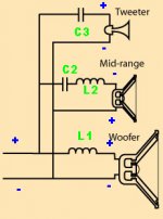
I began to design speaker with a calculator and my ears...
Pay attention to the polarity.
You can choose L1=2.2mH L2=0.47mH C2=15uF C3=2.2uF
This is a more elaborate crossover i done on a JBL TLX215 for a friend. It can work well on your speaker.

Attachments
- Status
- This old topic is closed. If you want to reopen this topic, contact a moderator using the "Report Post" button.
- Home
- Loudspeakers
- Multi-Way
- Repairing 3 way speakers (Looking for some help)