Hello, long time lurker would like to ask help from diyaudio gurus here :
I am trying to replicate a nice mtm center speaker with vifa P13WG-00-08 and D27, main problem is the only pair I can find here are A13WHs with 4 ohm impedance.
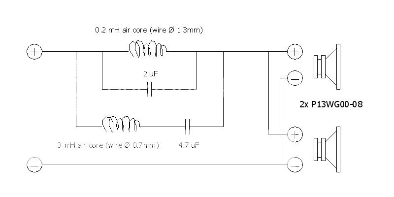
Assuming both models have exactly similar parameter except for impedance, how do I convert these values in following low pass crossover ?
Really appreciate any help or guidance as I have very little knowledge on electronics. Thanks much in advance.
cheers,
sm
I am trying to replicate a nice mtm center speaker with vifa P13WG-00-08 and D27, main problem is the only pair I can find here are A13WHs with 4 ohm impedance.
Assuming both models have exactly similar parameter except for impedance, how do I convert these values in following low pass crossover ?
Really appreciate any help or guidance as I have very little knowledge on electronics. Thanks much in advance.
cheers,
sm
Hi sm,
My gut tells me that you would drop the 0.2mH inductor down to 0.1mH, and then remove the rest of the components because they have no business being there? I'm really hoping someone else can shed some light on the reason those other components are wired in like that. I can't figure out what business they have being there.
Is your amp going to be alright with a 2 ohm load with those woofers in parallel? My personal approach would be to wire the woofers in series and use a 0.4mH inductor instead, resulting in a ~8ohm speaker.
That looks like a *really* odd design for a crossover - are you sure about the schematic?
You will want to put the A13WH's in series to get a 8-ohm load. Most HT amps won't drive a 2-ohm load in my experience.
This also means that you will likely need to pad the tweeter output down in order to match the woofers. At this point you are really better off throwing out the old design and starting from scratch. Perhaps using one of the simple crossover design tools.
Eg. http://www.diyaudio.com/forums/mult...designing-crossovers-without-measurement.html
Good luck,
-bill
Last edited:
That filter is just a contour shaper (I think 0.3mH is more proper than 3mH), so basically the P13 is run in fullrange, where the tweeter is crossed at the P13 natural roll-off frequency.
But A13 is a different driver than P13. I think A13 is more a midrange (P13 is more a midwoofer). So even the contour will be different (the above filter will be useless).
But A13 is a different driver than P13. I think A13 is more a midrange (P13 is more a midwoofer). So even the contour will be different (the above filter will be useless).
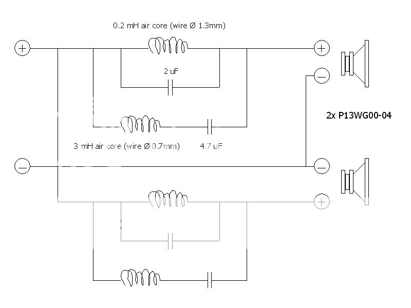
Thanks much for all your useful replies and suggestions ! To simplify, let's just assume that there are now two P13WG-04 or 4 ohms drivers with exact parameters (except impedance of course) to replace their 8 ohm brothers.
I'm very curious with resulting 'character' of 8 ohm woofers in parallel, if I could consider them as single 4 ohm driver that should make things easier, correct ? Do you guys think double crossover (one for each 4 ohm drvr) will accomplish the same purpose as original one with parallel 8 ohm drvrs ? [wishful thinking mode]")
As for that weird L-C connection, I already triple checked it, since at first I thought it was a zobel network wrongly connected. But it does look like a notch filter. Anyway the big L is actually 3mH (measured it, disconnected from xo) ... and tweeter xo is even more complicated for a 1st order config.
Again I really appreciate additional confirmation on above alternative double xo or other conversion ideas.
cheers,
salim sm
--------
From this Vifa model notes, hopefully the difference between A13 and P13 is only limited to basket material :
I'm very curious with resulting 'character' of 8 ohm woofers in parallel, if I could consider them as single 4 ohm driver that should make things easier, correct ? Do you guys think double crossover (one for each 4 ohm drvr) will accomplish the same purpose as original one with parallel 8 ohm drvrs ? [wishful thinking mode]
As for that weird L-C connection, I already triple checked it, since at first I thought it was a zobel network wrongly connected. But it does look like a notch filter. Anyway the big L is actually 3mH (measured it, disconnected from xo) ... and tweeter xo is even more complicated for a 1st order config.
Again I really appreciate additional confirmation on above alternative double xo or other conversion ideas.
cheers,
salim sm
--------
From this Vifa model notes, hopefully the difference between A13 and P13 is only limited to basket material :
An externally hosted image should be here but it was not working when we last tested it.
An externally hosted image should be here but it was not working when we last tested it.
anybody ?
fwiw, here's description of vifa tweeter models:
fwiw, here's description of vifa tweeter models:
An externally hosted image should be here but it was not working when we last tested it.
An externally hosted image should be here but it was not working when we last tested it.
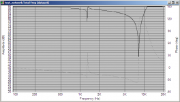
The 0.2mH 2uF LC circuit forms a high q notch at 7957Hz. This I would think would be a very narrow notch, and will be independent of the impedance of the woofers (ie it will make no difference if it is 4 ohms or 8 ohms) even if there was a 10 ohm resistor in parallel with the L and C, the Q of the filter would be 100!!! with no resistor in parallel the Q is theoretically infinite.
Tony.
Tony.
The 0.2mH 2uF LC circuit forms a high q notch at 7957Hz.
Tony.
Thanks Tony,
At first look I thought the "main" inductor for those woofers is the 0.2mH one, as it is a thick wired Solen made inductor, while the 3mH is made of thin wire, and in series with 4.7uF capacitor.
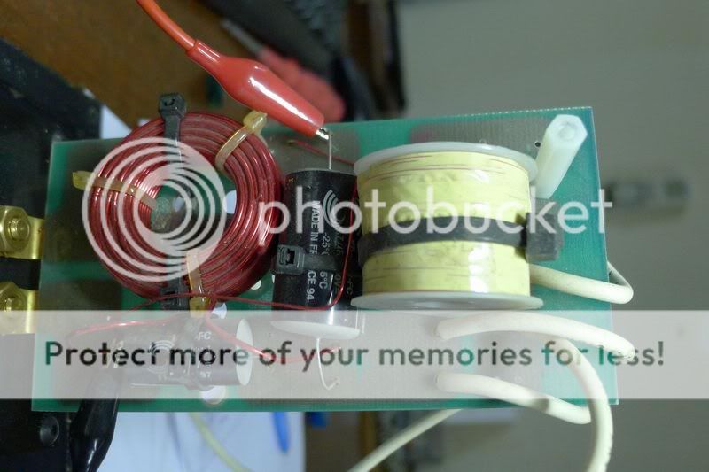
(pcb above is only for midbass, tweeter xo is in separate board)
Are these P13s driven full range or does that 0.2mH also serves as lowpass filter ? Iirc a 3mH value would be too low as a lowpass filter for a 5 inch driver.
Btw could you comment whether separate xo for each 4 ohm woofer on my drawing above will do the job in replacing one xo for 8ohm drivers in parallel ?
tia,
salim sm
I'm very curious with resulting 'character' of 8 ohm woofers in parallel, if I could consider them as single 4 ohm driver that should make things easier, correct ? Do you guys think double crossover (one for each 4 ohm drvr) will accomplish the same purpose as original one with parallel 8 ohm drvrs ?
The NOMINAL impedance of the woofers will have no serious effect on the response. It will only affect the minimum IMPEDANCE of the speaker. If your amp can handle half the impedance (around 2 Ohm at certain frequencies) then you can use the original filter.
Running dedicated (low pass) filter for each woofer will not improve the impedance (it might be slightly worse, and of course, more expensive).
The idea of running two woofers in parallel is so that each woofer will have lower SPL (compared to when single woofer is used) so the "breakup point" or peak or resonance is not quickly reached. But because there are two woofers the total SPL is higher than using single woofer. The price is the lower total impedance.
Running the two woofers in series will solve the low impedance issue but total SPL will be much lower.
Using lower impedance woofers may decrease the SPL but not significance. Using dedicated filter for each woofer may increase the SPL but not significance. Meaning that the original filter can be used for both approaches with no significance effect (on tweeter crossover).
That's ASSUMING that the woofers (P13WG-08 and P13WG-04) only differ in nominal impedance.
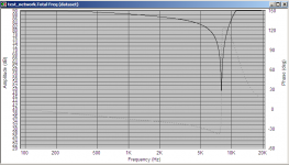
Hi nakman, I was uncertain what the 3mH and 4.7uF were doing so I decided to model the whole thing (first the notch then with the other as well) interestingly the notch didn't behave exactly as I thought. it actually rolls off from quite a low frequency.
This was done using my own woofers impedance (which is around 4 ohms), and a flat freq response.
1st with only the notch, second with 3mh and 4.7uF added.
Tony.
This was done using my own woofers impedance (which is around 4 ohms), and a flat freq response.
1st with only the notch, second with 3mh and 4.7uF added.
Tony.
Attachments
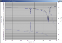
I posted the above quickly before going out. I've come back and scaled the impedance up and the impedance also makes a difference (which means that the above curves are somewhat dependent on the impedance of my morel MW144's which were the doner for the impedance curve I used in the sim.
Below the difference that 8 ohms vs 4 ohms makes is apparent. As you can see the notch frequency is unaffected, but the rolloff before the notch frequency is affected. The black curve is the 8 ohms and the blue curve is 4 ohms. I basically just scaled the 4 ohms impedance curve by addling 4.
I'm not sure about the putting a separate crossover on each driver. I can try simulating that to see what comes out I would be worried about the 2 ohm impedance though. 4 ohms is the nominal impedance, with a nominal impedance of 2 ohms it will almost certainly dip below that.
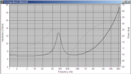
edit: note that my impedance data is closer to 3 ohms and 7 ohms too. scaled impedance curve used also attached.
Tony.
Below the difference that 8 ohms vs 4 ohms makes is apparent. As you can see the notch frequency is unaffected, but the rolloff before the notch frequency is affected. The black curve is the 8 ohms and the blue curve is 4 ohms. I basically just scaled the 4 ohms impedance curve by addling 4.
I'm not sure about the putting a separate crossover on each driver. I can try simulating that to see what comes out
I would be worried about the 2 ohm impedance though. 4 ohms is the nominal impedance, with a nominal impedance of 2 ohms it will almost certainly dip below that. edit: note that my impedance data is closer to 3 ohms and 7 ohms too. scaled impedance curve used also attached.
Tony.
Attachments
Last edited:
Hello, long time lurker would like to ask help from diyaudio gurus here :
Assuming both models have exactly similar parameter except for impedance, how do I convert these values in following low pass crossover ?
Your P13WG drivers are designed as mid woofers. They will work well in a MTM design.
The A13WH drivers are completely different. They are a midrange driver and are only suited to that role. They cannot be used in a MTM.
A crossover designed for the P13WG will not work for an A13WH.
Sorry to be so blunt.
Terry
Last edited by a moderator:
Thanks again Tony, Jay and Terry, for your time and explanation. Those are very helpful guides and hopefully I can build this nice center speaker in a week or two, despite lower sensitivity with midbass in series.Hi nakman, I was uncertain what the 3mH and 4.7uF were doing so I decided to model the whole thing (first the notch then with the other as well) interestingly the notch didn't behave exactly as I thought. it actually rolls off from quite a low frequency.
On A13 suggestion, I don't think I will need as much bass out of center channel as opposed to regular front speakers and put the emphasis on clear dialogues instead. Even the original speaker with P13 puts out less bass than B&W cc6 (eek), but to me its mids are more clear vs audience 52, which is quite a good show ... and that is my main reason in trying to duplicate this center speaker. By the way both P & A13 look exactly identical, and I sure hope that vifa model nomenclature is correct.
Will inform you again how the project goes, and maybe at the same time post comparison sweeps between original, clone and cc6.
cheers,
sm
Thanks again Tony, Jay and Terry, for your time and explanation. Those are very helpful guides and hopefully I can build this nice center speaker in a week or two, despite lower sensitivity with midbass in series.
With 2x A13-04 in series, the SPL will be more or less equivalent to the SPL of 1x P13-08. So compared to original speaker it will be almost 6dB down in SPL. This way you need also to bring down the sensitivity of the tweeter to match the new midbass SPL.
The above will change a few things in the cross frequency, so basically you need to design a new filter.
I have no experience with HT, but I think a center should be voiced to match the front speakers. May be your plan is still doable because I believe you are after the beautiful mid of the P13, even with lower sensitivity.
Parameters of a speaker are not only those reflected by the nomenclature. But an SPL chart must be somewhere on the net, and I think a A13 might have higher frequency extension than P13. If so, the natural roll-off of the A13 will not cross at the expected frequency as requested by the tweeter filter.
Better find out about this SPL chart (or better frd/zma files) first, then it is not difficult to clone the speaker. But this will be a new design.
Hello fellow neighbourI have no experience with HT, but I think a center should be voiced to match the front speakers. May be your plan is still doable because I believe you are after the beautiful mid of the P13, even with lower sensitivity.
Yes you are correct. And this is not meant for a full scale HT, just for watching movies in bedroom thru a panasonic HT 'system'
By the way front speakers are Minium bookshelves which also contain vifa 4inch "woofer" with surprising bass and what looks like seas tweeter (no marking whatsoever).Thanks again. I have no high hopes for cloning accuracy, since I don't have a D27 tweeter at this moment. I plan to match resulting mid rolloff with simple 1st order plus L pad on an mdt29.Better find out about this SPL chart (or better frd/zma files) first, then it is not difficult to clone the speaker. But this will be a new design.
salam,
sm
@Wintermute. Is there any chance you could double the capacitances and halve the inductances then switch to four ohms?
@nakman. I'm concerned about the phase/driver offset. Is there a chance you could disconnect one woofer then listen above and below the centre line (and all in between) to find the angle that it sounds best. You may need to adjust the driver distances when you build. It may help if you can pad down the tweeter a little. (Of course, the different driver makes this seem a little pointless)
@nakman. I'm concerned about the phase/driver offset. Is there a chance you could disconnect one woofer then listen above and below the centre line (and all in between) to find the angle that it sounds best. You may need to adjust the driver distances when you build. It may help if you can pad down the tweeter a little. (Of course, the different driver makes this seem a little pointless)
- Status
- This old topic is closed. If you want to reopen this topic, contact a moderator using the "Report Post" button.
- Home
- Loudspeakers
- Multi-Way
- noob needs help converting mtm crossover