I don't think this is an everyday type of problem, and I admit it is a problem of my own making.
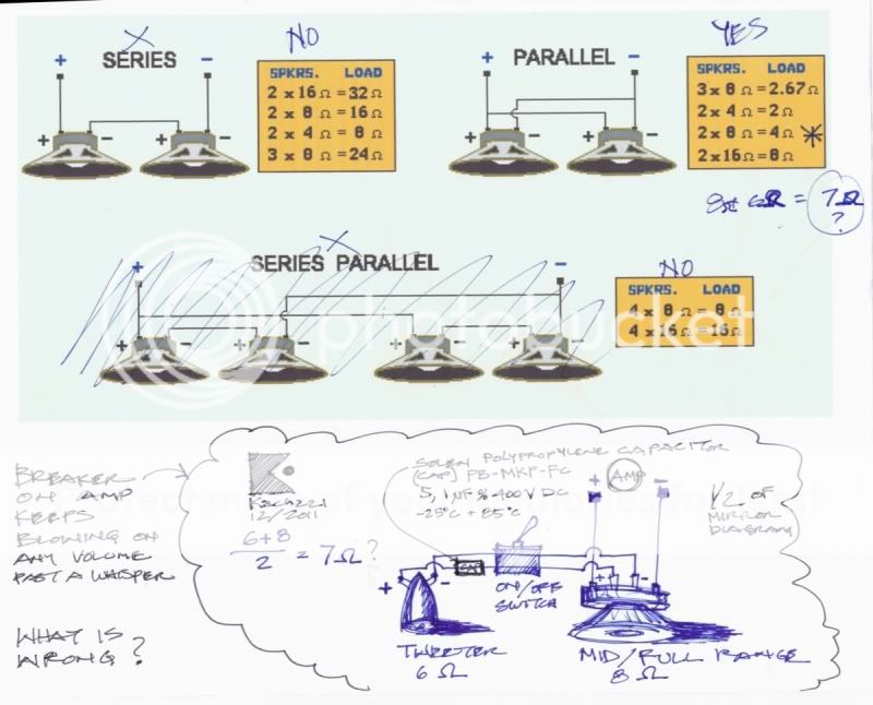
I built a limited range/full range speaker using a single mid/woofer driver. It operated fine. There was a minor experiment on the dust cap to increase the high frequency, it didn't quite work as hoped but got me part of the way there.
In order to judge how much a tweeter would help the high end, I decided to add one. I then had this big idea, why not make it switchable?
What I want is to operate in full range with a single driver, then at the flip of a switch the tweeter becomes activated.
The problem is, that no matter what I do I cannot play louder than a whisper before the protection circuitry in my receiver shuts down the amp.
I have unknowingly built a short circuit or open circuit somehow.
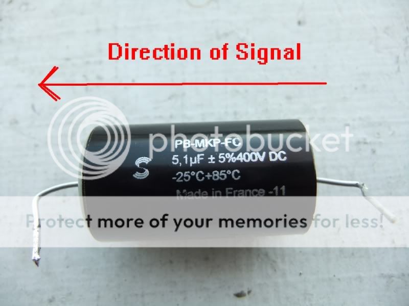
The capacitor I picked out might be the problem. Either I selected the wrong type, or it is directional and I have it backwards, I have no clue.
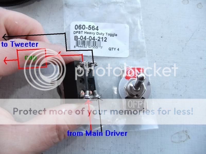
The toggle switch I picked out might be the problem, but I have tried several types and they all suffer the same ills.
Maybe I should not be mixing a 6 ohm tweeter with a 8 ohm mid/woofer.
Please review this problem and ask any questions you may have.
I do have some crossovers laying around, but I did not want to build a traditional 2-way. I want to operate as full range, then flip the toggle and be full range plus a frequency protected tweeter.
Stereo pictures by kach22i - Photobucket
I built a limited range/full range speaker using a single mid/woofer driver. It operated fine. There was a minor experiment on the dust cap to increase the high frequency, it didn't quite work as hoped but got me part of the way there.
In order to judge how much a tweeter would help the high end, I decided to add one. I then had this big idea, why not make it switchable?
What I want is to operate in full range with a single driver, then at the flip of a switch the tweeter becomes activated.
The problem is, that no matter what I do I cannot play louder than a whisper before the protection circuitry in my receiver shuts down the amp.
I have unknowingly built a short circuit or open circuit somehow.
The capacitor I picked out might be the problem. Either I selected the wrong type, or it is directional and I have it backwards, I have no clue.
The toggle switch I picked out might be the problem, but I have tried several types and they all suffer the same ills.
Maybe I should not be mixing a 6 ohm tweeter with a 8 ohm mid/woofer.
Please review this problem and ask any questions you may have.
I do have some crossovers laying around, but I did not want to build a traditional 2-way. I want to operate as full range, then flip the toggle and be full range plus a frequency protected tweeter.
Stereo pictures by kach22i - Photobucket
Last edited:
Isn't this one woofer though, and one tweeter? If so then the impedance would be as for the woofer, the tweeter is less of an issue as long as it is functioning and properly connected and crossed.
The only errors that spring to mind are incorrect usage of the switch, a broken driver, or a physical short to the body of the woofer etc.
You only need one pole of the switch to be used (as long as the cables are not hanging loose). This would also reduce the contacts count which is a good thing.
Capacitors are not directional. Some are polarised, which means they need to see a some DC to function correctly and they are usually marked accordingly. When it comes to a signal, they are the same either way. There are some specialty capacitors which claim to work better one way over the other but this is neither critical, nor significant.
You nailed it sofaspud.Your parallel impedance formula is all wrong. The correct formula is the product of the values divided by the sum of the values - in your case 48/14=3.4 ohms. Your amp probably doesn't like seeing a load like that.
How do I fix this, and what will the new impedance be?
Switch the positive with the negative leads on one of the drivers? Which one, the main or the tweeter?
What will the impedance be if in Series?
.................................................
AllenB, I do have some single pole toggle switches. I considered putting only the red wire positive lead though the toggle switch and running the black wire negative as a by-pass. Will this be better, if so then why? Just because of fewer connections and switching?
Last edited:
That's all...connections foul and fail. If I were in your position, I'd measure the resistance of the tweeter voice coil to determine it is functioning correctly, then hardwire it without the switch. I'd measure the resistance of the woofer with all else wired up as well simply to cover all possibilities.
Your impedance is not like a resistor. It will vary over the spectrum. The woofer will have a high impedance at higher frequencies due to the voice coil inductance. The tweeter will have a higher impedance down low due to the coupling capacitor. In all likelyhood, at no point in the spectrum will they actually be significantly in parallel, so to speak.
Your impedance is not like a resistor. It will vary over the spectrum. The woofer will have a high impedance at higher frequencies due to the voice coil inductance. The tweeter will have a higher impedance down low due to the coupling capacitor. In all likelyhood, at no point in the spectrum will they actually be significantly in parallel, so to speak.
I've just read from a couple of sources that:
To get to a 8 ohm load, where in my diagram would I add a resistor and do the least amount of signal degradation?
What rating, grade and type of resistor?
I should note that the receiver shuts down at low volume no mater if the tweeter is switched in the circuit or not. This makes no sense to me.
I would understand when a greater load (lower impedance of 2 drivers in Parallel) is created when the tweeter is switched in, but how or why is the tweeter affecting the load when switched out?
I will reconsider the toggle switch hook up per AllenB's comments, something is not right according to how I intended this to work, or think it should be working.
Placing a resistor before the driver will increase impedance.......
To get to a 8 ohm load, where in my diagram would I add a resistor and do the least amount of signal degradation?
What rating, grade and type of resistor?
I should note that the receiver shuts down at low volume no mater if the tweeter is switched in the circuit or not. This makes no sense to me.
I would understand when a greater load (lower impedance of 2 drivers in Parallel) is created when the tweeter is switched in, but how or why is the tweeter affecting the load when switched out?
I will reconsider the toggle switch hook up per AllenB's comments, something is not right according to how I intended this to work, or think it should be working.
I've just thought of an alternate to adding a resistor or two. How about adding a rear firing tweeter (out of phase of course)?
Is this the correct math if the new tweeter is 4 ohms?
(8 x 6) 4
_________
8 + 6 + 4
............................................................................
192
_______
18
.............................................................................
= 10.667 ohms?
I'd rather use a resistor, but I'm considering all options.
That suggests to me that there is a wrong connection somewhere. After all, didn't the mid/woofer work by itself before the mod?I should note that the receiver shuts down at low volume no mater if the tweeter is switched in the circuit or not. This makes no sense to me.
Yes, while you were typing this, I eliminated the toggle connections and went all the way back to the terminals/speaker binding posts. I had added these posts after my initial listening test, did them at the same time I installed the tweeters.That suggests to me that there is a wrong connection somewhere. After all, didn't the mid/woofer work by itself before the mod?
It was bad binding post detail/connection. These are the fancy long gold posts, not the plastic nut type. I did not mount them in the usual fashion which is thru-cabinet. I mounted them externally on the back using an aluminum angle mounting flange with two holes. The entire angle was double coated with liquid electrical tape, I used large steel nuts as a spacers because of threading.
This liquid tape and or the steel nuts found a small amount of conductivity which bridged the two posts via the mounting flange.
I have now placed foam rubber furniture dots (insulators) on each side of my mounting flange and punctured a hole which the binding posts go through. The binding posts wobble a bit now but are well insulated.
Everything is rock'n now, the tweeter toggle switches work too.
I've have now discovered that I do indeed need the second pair of caps I purchased to tone down the tweeters. Starting that right now.
As soon as these speakers are debugged I'll be hooking them up to my big tube amp and really see what they can do. Going down to 3.4 ohms might not be a big issue, my old Martin Logans go down to 2 ohms with this tube amp.
Thank you everyone for holding my hand on this, I'm learning.
")
Last edited:
While you should avoid going too low in impedance with transistors, you should avoid going too high with valves, although they tend to be more rugged either way.
Why not try using a resistor in series with the tweeter to quieten it down a bit? and don't calculate the tweeter and woofer in parallel as doing so is incorrect.
Why not try using a resistor in series with the tweeter to quieten it down a bit? and don't calculate the tweeter and woofer in parallel as doing so is incorrect.
- Status
- This old topic is closed. If you want to reopen this topic, contact a moderator using the "Report Post" button.
- Home
- Loudspeakers
- Multi-Way
- Request for wiring help - toggle switch and cap involved