Hello,
My measurement of Seas T18REX/XFC (H1353) tweeter FR doesn't match Seas spec and it doesn't match what Zaphaudio (zaphaudio.com/tidbits/H1333-tweeter-FR.gif) has measured either.
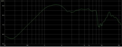
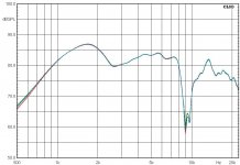
I get huge dip spanning from 8kHz to 12kHz as Seas spec doesn't show much dip at all and Zaphaudio shows much smaller dip around 8-10kHz. I got same result measuring two different drivers.
Also I found somewhere Ascendo C5 FR which uses Seas coax and that FR (tweeter dip part) looks more like what Zapfaudio measured.
What can explain the different results I get?
Thanks,
Timo
My measurement of Seas T18REX/XFC (H1353) tweeter FR doesn't match Seas spec and it doesn't match what Zaphaudio (zaphaudio.com/tidbits/H1333-tweeter-FR.gif) has measured either.
I get huge dip spanning from 8kHz to 12kHz as Seas spec doesn't show much dip at all and Zaphaudio shows much smaller dip around 8-10kHz. I got same result measuring two different drivers.
Also I found somewhere Ascendo C5 FR which uses Seas coax and that FR (tweeter dip part) looks more like what Zapfaudio measured.
What can explain the different results I get?
Thanks,
Timo
Attachments
A number of possibilities.
1. The smoothing that has been used could be different.
2. An on-axis dip can be strongly focussed there, try some of the off-axis measurements.
3. Manufacturing tolerances.
4. Gating a reflection free zone.
5. Diffraction from your baffle, or your mounting procedure.
6. Your microphone calibration.
7. Your microphones physical construction, including its shape, and its mounting procedure.
8. measuring distance.
Not necessarily in that order.
2. An on-axis dip can be strongly focussed there, try some of the off-axis measurements.
This one I think is most likely, given the coaxial nature. If it clears up off axis I wouldn't pay these dips much mind; just design "pretending" they're flat.
...for example an on-axis null due to a mouth reflection at the axial distance from the dome to the mouth?
Maybe tipo1000 could run some damping material over and within the roll surround and try again. If it is this it shouldn't be as strong off-axis as well but perhaps designs with this unit would work out better off-axis for other reasons anyway.
Maybe tipo1000 could run some damping material over and within the roll surround and try again. If it is this it shouldn't be as strong off-axis as well but perhaps designs with this unit would work out better off-axis for other reasons anyway.
2. An on-axis dip can be strongly focussed there, try some of the off-axis measurements.
5. Diffraction from your baffle, or your mounting procedure.
Those will make the most significant difference, assuming you are sufficiently skilled at taking these measurements.
You will only get the same result if your measurement setup is the same. I believe that Zaph does describe his setup here Zaph|Audio
Thanks for all suggestions.
I did more measurements at 0.5m, 1m and 1.8m distances.
The wide "W" shaped dip I got earlier @1m seems disappear @1.8 and comes one deep dip much like in other guys measurements.
I also moved the mic 1 inch around on axis to see if it affects that mic is not exactly dead on, but it didn't seem to make difference.
I'm not worried about other differences; they can be because of my speaker enclosure.
Thanks,
Timo
Attachments
This problem is visible in the measurements that others have done. Even if the apparent Q of the dips looks worse for you it may not actually be worse. Your smoothing parameters may not be the same as previously used either.
I would be trying to achieve a measurement that is consistent with one of the previously done ones and I'd start off-axis. Eg: 0.5m at 30 degrees.
It's possible this could be diffraction from the mid cone former. If it is it may be somewhat reducible with treatment.
I would be trying to achieve a measurement that is consistent with one of the previously done ones and I'd start off-axis. Eg: 0.5m at 30 degrees.
It's possible this could be diffraction from the mid cone former. If it is it may be somewhat reducible with treatment.
One source of SPL inaccuracy might be your mic setup. Some questions in that direction:
How is your mic mounted?
Which mic do you use?
Do you have other tweeters you can verify your test setup with (against others' measurements)?
What about impedance measurements? Do they match up (sanity check)?
How is your mic mounted?
Which mic do you use?
Do you have other tweeters you can verify your test setup with (against others' measurements)?
What about impedance measurements? Do they match up (sanity check)?
Hello again,
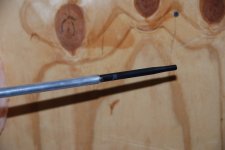
My measurement mic is about 15cm long (purchased from Clio) and it's 'extended' to 1m long with an aluminum tube. So the mic clamp is 1m from mic capsule.
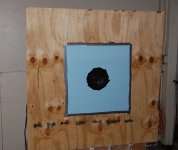
I made some more measurements based on ideas given here. I made crude/quick 1.2m by 1.2m baffle, driver was placed in the middle. 0deg measurements and impedance measurements were taken with both drivers (TW1 and TW2); two different speakers. All measurements taken @1.8m.
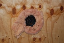
Speakers were installed on top of plywood baffle creating ~5mm step from speaker flange to plywood. Some measurement were taken having insulation foam around speaker. I also tried having 5mm thick styrofoam 'ring' around speaker to minimize the effect of that 5mm step.
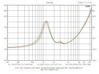
Impedance measurements (taken without foam or styrofoam ring) look normal, I guess, for both speakers. Small glitch at ~3k in both which shows also in FR taken with foam ring but do not show in FR taken with styrofoam ring so the cause of that glitch seems to be 5mm step.
I'm not sure what I can learn from the other measurements but hopefully you can shed some light.
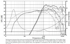
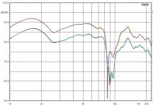
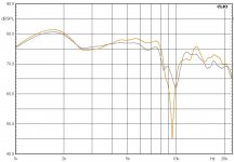
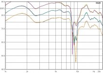
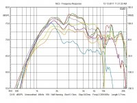
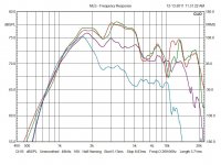
Colors are same in all pics. All data is same in all pics, just different curves selected for clarity:
RED: TW1 @1.8m 0deg
GREEN: TW2 @1.8m 0deg
YELLOW: TW1 @1.8m 0deg with insulation foam ring
ORANGE: TW1 @1.8m 30deg with insulation foam ring (couldn't repeat this with 60deg because foam came in between TW and mic)
PURPLE: TW1 @1.8m 30deg
CYAN: TW1 @1.8m 60deg
GREY: TW1 @1.8m 0deg with styrofoam ring
Big thanks for your help,
Timo
My measurement mic is about 15cm long (purchased from Clio) and it's 'extended' to 1m long with an aluminum tube. So the mic clamp is 1m from mic capsule.
I made some more measurements based on ideas given here. I made crude/quick 1.2m by 1.2m baffle, driver was placed in the middle. 0deg measurements and impedance measurements were taken with both drivers (TW1 and TW2); two different speakers. All measurements taken @1.8m.
Speakers were installed on top of plywood baffle creating ~5mm step from speaker flange to plywood. Some measurement were taken having insulation foam around speaker. I also tried having 5mm thick styrofoam 'ring' around speaker to minimize the effect of that 5mm step.
Impedance measurements (taken without foam or styrofoam ring) look normal, I guess, for both speakers. Small glitch at ~3k in both which shows also in FR taken with foam ring but do not show in FR taken with styrofoam ring so the cause of that glitch seems to be 5mm step.
I'm not sure what I can learn from the other measurements but hopefully you can shed some light.
Colors are same in all pics. All data is same in all pics, just different curves selected for clarity:
RED: TW1 @1.8m 0deg
GREEN: TW2 @1.8m 0deg
YELLOW: TW1 @1.8m 0deg with insulation foam ring
ORANGE: TW1 @1.8m 30deg with insulation foam ring (couldn't repeat this with 60deg because foam came in between TW and mic)
PURPLE: TW1 @1.8m 30deg
CYAN: TW1 @1.8m 60deg
GREY: TW1 @1.8m 0deg with styrofoam ring
Big thanks for your help,
Timo
Attachments
-
 Impedance for TW1 and TW2.jpg149 KB · Views: 219
 -
 Everything.jpg186.3 KB · Views: 212
 -
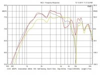 TW1_0deg TW1_0deg_insul TW1_0deg_styro.jpg147.8 KB · Views: 209
 -
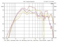 TW1_0deg TW1_30deg TW1_0deg_insul TW1_30deg_insul.jpg163.3 KB · Views: 211
 -
 TW1_TW2_0deg TW1_30deg TW1_60deg.jpg165.5 KB · Views: 214
 -
 Mic.JPG163.5 KB · Views: 87
 -
 Baffle and styrofoam ring.JPG393.2 KB · Views: 95
 -
 Insulation foam.JPG286 KB · Views: 105
Looking at the middle graph, and assuming the colors show up correctly on my laptop screen (red, yellow, grey? the yellow looks lightgreen on my screen),
both damping-materials make the dip at ~6 Khz disappear, while the ~10 Khz dip becomes much deeper.
It indicates to me that the dips come from the discontinuities caused by the shape of the midwoofer's surround, the transition
from the surround to the chassis and the transition from the chassis to the baffle.
(i hope my choice of words is clear enough)
Put in other words, the shape of the surround and the transition from surround to chassis to baffle make for a rather poor waveguide/baffle for the tweeter to work in.
This is most probably one of the reasons why Kef f.i., as soon as budget permits, design their systems in such a way
that they can avoid large excursions of the cone, so they can use a flat surround.
Apart from countersinking the chassis, you could experiment with the location and shape of your damping-material
(a solid material could probably work just as well) to make the transition from surround to chassis to baffle as smooth as possible,
and measure your results.
Klaas
Your new measurements are showing some consistency with the earlier examples and I think you should begin move forward on this. One word of assistance on your large baffle measurements though. You are trying to take the tweeter in half space so your measuring distance needs to be far away as far as the tweeter is concerned, but close as far as your baffle is concerned. You might try something more like 50cm. When you measure in the final speaker configuration, of course, you'll want to be back far enough to include the baffle.
I guess now though you'll want to experiment as kvholio has shown.
I guess now though you'll want to experiment as kvholio has shown.
- Status
- This old topic is closed. If you want to reopen this topic, contact a moderator using the "Report Post" button.
- Home
- Loudspeakers
- Multi-Way
- Seas coax (H1333/H1353) tweeter measurement data doesn't match