Whatever phase difference "problem" arise with passive crossovers, the same issues happen with active x-overs.Just heard a few things about phase differences at the crossover point just wondered if this is the case as I've looked into a few simulations. Can we ignore this problem with active crosssovers?
Thanks
Boscoe.
"Active" has a few advantages over "passive" but that doesn`t mean that "active" voids the usual and inevitable frequency / phase response relationship of passive filters (unless not so common "substraction" type active crossovers are involved).
Even with a subtraction filter phase is important because drivers may not be (probably are not in most cases) time aligned, introducing additional phase shift.
A crossover can't really be designed without measuring the actual phase shift of each driver on the design axis so that all contributing factors towards phase (crossover response, driver response, time alignement) are taken into account.
Ignore the phase response and chances of getting the wanted response are slim...
The phase response of drivers and filters can be seen with dual FFT test gear like Smaart or TEF.How do you go about obtaining the phase difference? What's the best way of minimising the difference? Is it only remedied by delays?
Physical offset, digital delay, all pass filters, using different filter types and slopes for the lower and upper crossover, in and out of band EQ may be used to achieve the desired acoustic crossover and phase alignment.
The "best way" would be a matter of opinion and available options with the gear chosen, and the reproduction use. There are many ways to skin the phase cat.
Art
You HAVE to stop thinking "phase", and start to think in units of "time".
Phase does, with the addition of a few more parameters GIVE you "time", but it is not equal to "time".
The 6" driver is deeper set, the sound at ~2kHz may eminate from a point well behind the speaker baffle surface.
The Fountek has a radiation center that's about 1/2" behind the baffle surface.
At 2200Hz, one inch difference is the same as a 60º phase shift.
The easiest way to optimize phase shift in reality is to adjust the slopes of the x-over until you see that the individual drivers sum POSITIVE at all points, and that the addition at the exact x-over point is as close to 6dB higher than the individual drivers as possible.
It's also important to remember that the electrical phase angle has to be combined with the driver's natural phase angle to make a meaningful simulation. The RESULT of x-over + driver response gives you the phase.
This is especially important when you cross a tweeter close to its' own fall-off point. Most tweeters have a 2'nd order slope with a certain resonance point and Q. When you combine this with a 2'nd order x-over you get a 4'th order system.
How do you go about obtaining the phase difference? What's the best way of minimising the difference? Is it only remedied by delays?
You need to measure the driver and crossover response in a way that shows the phase as well as amplitude. Something like Holm impulse will do that. When you see the phase curves of the various sections (woofer, tweeter) you will see how close together or far apart they are.
Phase is just signal arrival time expressed in terms of degrees of a circle. The two wavefronts (woofer/tweeter) can arrive in phase (0 degrees, 360 degrees, etc. apart) in which case they will add constructively. If they are more than 90 degrees apart they will cancel leaving a hole in the response in the crossover region (although they may add okay at some other angle).
The phase shift (or rotation) is inherent in any rolloff due to passive filter, active filter, or even the natural rolloff of the drivers. Also, because the woofer usually has more depth than the tweeter, it will have considerable extra phase shift.
The objective of speaker design, in a nutshell, is to manipulate the crossover response so that driver and crossover together have the right amplitude and phase shift to add together seamlessly.
David
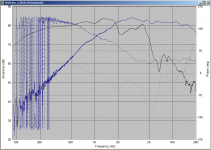
For a visual example (I need to see pictures ") ) have a look at my measurements below.
) have a look at my measurements below.
The original measurements were taken using holm impulse exported and imported into speaker workshop. measurements for both mid basses and tweeter were taken with the mic in the same place. Holm was set to zero-locked after taking the tweeter measurement (this ensures that the time zero (and hence phase) stays constant relative to each driver.
The crossover was then modelled in speaker workshop using impedance measurements and the spl measurements.
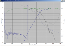
The very first crossover did not take into consideration phase (in a serious way), and I was not happy with the results. the second one did and the results are in the second attachment (and I'm very happy both subjectively and objectively).
What you see in the second attachment is I believe the sort of thing to aim for (the phase is the dotted lines) note how that track closely to each other from around 1.3K to a bit below 5K. No it wasn't easy getting that, but I think it was worth the effort. The difference with this new crossover compared to the first is like chalk and cheese!
How much of it is down the the phase, and how much due to other factors I'm not sure, but I do think that the matching of phase through the crossover region (crossover point 2.8Khz) is more than likely one of the reasons that this crossover is subjectively much better than my first effort.
Now that was with a passive crossover. How do you think that those drivers will sum with an active crossover that for example, simply applies a specific electrical 4th order crossover at 2.8Khz? I strongly suspect it won't sound anywhere near as good
Tony.
) have a look at my measurements below. The original measurements were taken using holm impulse exported and imported into speaker workshop. measurements for both mid basses and tweeter were taken with the mic in the same place. Holm was set to zero-locked after taking the tweeter measurement (this ensures that the time zero (and hence phase) stays constant relative to each driver.
The crossover was then modelled in speaker workshop using impedance measurements and the spl measurements.
The very first crossover did not take into consideration phase (in a serious way), and I was not happy with the results. the second one did and the results are in the second attachment (and I'm very happy both subjectively and objectively).
What you see in the second attachment is I believe the sort of thing to aim for (the phase is the dotted lines) note how that track closely to each other from around 1.3K to a bit below 5K. No it wasn't easy getting that, but I think it was worth the effort. The difference with this new crossover compared to the first is like chalk and cheese!
How much of it is down the the phase, and how much due to other factors I'm not sure, but I do think that the matching of phase through the crossover region (crossover point 2.8Khz) is more than likely one of the reasons that this crossover is subjectively much better than my first effort.
Now that was with a passive crossover. How do you think that those drivers will sum with an active crossover that for example, simply applies a specific electrical 4th order crossover at 2.8Khz? I strongly suspect it won't sound anywhere near as good
Tony.
Attachments
Last edited:
Speaking strictly as a total newb: I do wonder why it's most common to mount the drivers on a single flat baffle, since that just makes the job harder. Since it's DIY anyway, wouldn't it be vastly easier to start by first physically aligning the drivers' acoustic centers (and then do a simpler crossover)? Of course this would likely mean using a widebander as either the woofer or tweeter (or both).
For example, very simplistically, mount the woofer in a box, but the tweeter in a board, then slide the tweeter around until its acoustic center is aligned with the woofer (e.g., by perhaps playing a tone at the anticipated crossover point, very low SPL, and move the tweeter and woofer create a null at that frequency and at the listening position).
And then assuming the tweeter can handle it, do a simple first-order series crossover (and don't play at SPL's louder than the system can now handle).
I'm sure there are many reasons (e.g., desire to avoid widebanders?) but I do wonder why the simpler path isn't seen more often. Perhaps people feel a higher-order crossover ends up sounding better at the SPL's they listen at? Or that it extracts more potential performance from the system? Yet many do not listen at high SPL's.
The only thing that drops out of the equation(s) when going from
passive to active filtering is the interaction between the filter and driver's impedance.
This doesn't necessarily make filterdesign easier imo, a lot of times you can make a passive filter work WITH the driver's impedance to achieve the desired target response.
passive to active filtering is the interaction between the filter and driver's impedance.
This doesn't necessarily make filterdesign easier imo, a lot of times you can make a passive filter work WITH the driver's impedance to achieve the desired target response.
(Rjbond) You will find proponents of both kinds of system design on this forum. Time allignment can be made to work but it will present a couple of difficulties. First, stepped baffles generally give rougher response. Second, true first order rolloff, being a combination of the electrical and the acoustical is difficult to achieve.
I've always found that using a 2nd or 3rd order electrical gave enough phase shift to work well with the typically displaced acoustic centers of a flat baffle. In that case getting the acoustic centers alligned wouldn't help and would likely hinder (Wintermute's example shows exactly what you can achieve in phase overlap without true time allignment).
Watch out for those who will tell you that first order electrical (without considering the additional phase shifts always present) confers any benefits.
David S.
How steeper you cross the bigger the phase shift till you have opposite phase and you can switch + and -.How do you go about obtaining the phase difference? What's the best way of minimising the difference? Is it only remedied by delays?
That is reason why some favor 1 order filter with low phase shift.
And using series filter helps to have the same phase shift for both drivers at the same time with good alignment on the baffle a good solution.
Stepped baffles and high order filters are not mutually exclusive, time aligning two drivers isn't always done in an attempt to go for some sort of "transient perfect" 1st order crossover. In fact I think true acoustic 1st order crossovers are a flawed idea.
Nice on paper perhaps purely from a filter summing perspective, but few drivers will perform well under those circumstances, and certainly won't perform nearly as well (especially large signal performance) as they will with steeper slopes. You end up sacrificing things that matter for things that don't. You also end up with a vertically offset lobe with an off-axis peak at the crossover frequency.
The other problem with stepped baffles is you can really only do it successfully with directivity controlled drivers. Putting a standard dome tweeter on a stepped baffle or small separate "pod" enclosure set back from the main baffle is going to be a nightmare of diffraction and reflection off the main cabinet.
A waveguide tweeter can be used in this application with a bit of care of rounding of edges, as the built in directivity is usually sufficient to minimize diffraction from the stepped baffle. On the other hand a deep enough waveguide may not need a stepped baffle in the first place - depending on the driver its being mated to they may be close to acoustically aligned mounted on a flat baffle, and this is the best situation of all.
Last edited:
Okay so now I am quite confused. Phase dosen't matter? It's all about time alignment? I am hopefully going to be using a minidsp crossover so I was thinking wacking some high order crossovers on then playing with a bit of delay on each channel to get a good response while measuring it all the time? Does this sound like a reasonable plan?
Thanks for the replies so far.
Thanks for the replies so far.
Okay so now I am quite confused. Phase dosen't matter? It's all about time alignment? I am hopefully going to be using a minidsp crossover so I was thinking wacking some high order crossovers on then playing with a bit of delay on each channel to get a good response while measuring it all the time? Does this sound like a reasonable plan?
Thanks for the replies so far.
Phase shift is a time alignment problem.
A phase shift of, lets say 90 degrees is the same as 1/4 of the period-time of that frequency where this 90 degree phase shift is.
1/4=90/360
360 degree is one hole cycle of a period.
So the time difference is (1/frequency)x(1/4)= time alignment at that point.
The problem is this time alignment changes with phase shift, the phase shift changes with passing the XO point. And then the impedance of the woofer increases that also is to be looked at with passive XO also active it keeps the inductive character.
Last edited:
Sorry yeh I do get that so you are talking about the difference in voice coil depth? Do I need to take driver phase itself into account too?
So lets assume I have my tweeter 10cm infront of my woofer and the crossover is at 2.2KHz. So that has a wave length of 15.6cm so the tweeter has positive phase of ~+240 degrees or 0.5ms so I would set a delay of 0.5ms on my crossover for my tweeter? In the datasheet for the M6a it says it's out of phase by +30 degrees out of phase and assume my tweeter is zero out of phase it is now effectively +210 degrees out? So would equate to less delay?
But what I don't get is, if you say time alignment and phase difference are the same thing, if in the datasheet the woofer is ahead in phase by 30 how can it be playing frequencies before they have reached the voice coil? Or am I totally missing the point? Does the phase shown in the datasheet give me phase between sound radiated and electrical arrival of the signal to the voice coil?
Also I'm calculating the delay as if the sound was travelling through air but it's not, it's travelling through the voice coil through the coil into air at the same depth as the the tweeter. As sound travels much faster through solid objects there's hardly gonna be that much of a delay.
Last edited:
- Status
- This old topic is closed. If you want to reopen this topic, contact a moderator using the "Report Post" button.
- Home
- Loudspeakers
- Multi-Way
- Driver phase difference at crossover point.