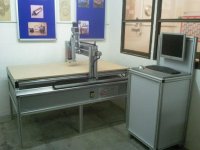
OK well I guess the best place to start with is the machine.
Mine is similar to this model from Strike except that has 1450x850x150 working area and mine is 1220x1220x200 with an enclosure covering the top section. Other than that they're identical(EDIT: Mine doesn't have the 4th axis either).


Here are the specs of the model:
Mine is similar to this model from Strike except that has 1450x850x150 working area and mine is 1220x1220x200 with an enclosure covering the top section. Other than that they're identical(EDIT: Mine doesn't have the 4th axis either).
Here are the specs of the model:
- Y dual 4nm motors
- X 4nm motor
- Z 3nm motor
- 4 axis integrated control box with interface spindle control
- 36V PSU
- 16x10mm anti backlash ball screws
- 25x10mm ball screws
- Precision supported linear rail
- Quick release cables
- Kress spindle mounts 43mm
- Kress milling spindle (FME 1050F)
I also found out besides Mach 3 it comes with a copy of Vectric 2D CAD CAM but am told this isn't much use for 2.5D.
I understand this isn't an industrial machine and is hobby orientated and I'm fine with that. I only ever plan to put MDF, wood and acrylic through it. Maybe when I'm more confident I'll have a go with some soft grade aluminium but it will be light duty and rare.
I'd appreciate if you can see any significant short comings with the machine but please bear in mind my requirements also, I'm not trying to gouge out 18mm depth at 100mm/sec here")
Also any advice on what the machine looks like it could handle in terms of the feed rate and cut depth in say MDF would be nice too.
One of my main concerns was noise so that's why the Kress was selected. I couldn't stretch the budget to a water cooled spindle and the powerful air cooled spindles are very noisy by most accounts. What I didn't want was to have the machine deafen me whilst I worked on other things since its all in the same room. I'll probably still need to wear ear defenders though.
I was looking at a rack and pinion machine from Marchant Dice but something about the guy I spoke to put me off. I got the sense he was telling me what I wanted to hear in order to get a sale and wasn't as helpful or open as Michael at Strike.
Attachments
I'm sure once I start playing around these questions will begin to answer themselves but for starters:
- For multi-sided parts how do I set the start point once the work piece is moved and flipped over? It has to be exact. The baffle for example requires this.
- Strike sell sensors to set positioning, are these useful or is there a simpler and cheaper method?
That machine looks very reasonable. There are definitely better ways to build, but they're usually more expensive so it's a pretty straight forward trade off. For example dual rack and pinion on the x axis would typically provide more speed out of the same size stepper motors and give a more useful force vs speed curve, but you'd need an extra motor and motor driver, different bearing arrangements, etc.
The high speed spindles can be much quieter, but you'll still get a ton of noise from the bit cutting the material.
For multisided parts that you reposition, there are several methods for resetting your work coordinates. You can use an edge finder, you can make a touch probe fairly cheaply (search cnczone), or you can make fixturing to locate the parts and use multiple work offsets as you move the part. There are probably lots of other ways as well. The simplest cheap method is probably to make your own touch probe. You can use a conductive piece of material of a known size placed against the part, for example a 1-2-3 block. You run a wire from this back to your controller. Then another wire from your spindle on a point that has electrical contact to the tool. Then you can setup a script to have the machine move until contact is detected between the tool and the block. Then an offset is applied to account for the diameter of the tool and the size of the block. Depending on the shape of your part, you could also use a piece of aluminum angle that fit against the corner of the part. Then you'd touch off the tool on one side of the angle in the x direction and the other side for the y. If you program so your z reference is the bottom of the part (the bed of the machine) that wouldn't change. There are lots of variations on how to do this. Different ways make more sense for different styles of parts.
Well... my $0.02...
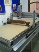
From the attached images, I'd say that the gantry looks a little under supported. At 200mm tall it might flex a little more than desired (unless the 200mm z option has more bracing).
Steppers. Nothing wrong in principle, but if you push them too far you risk missing steps (the controller thinks the machine's moved, but actually a stepper 'missed a beat' and you're not quite where you thought you were). Hopefully they'll have guidelines for safe cutting speeds & feeds in different materials.
The Kress spindle is interesting (I've not seen that before). If it were a 3 phase unit, then I'd say fine - I've seen 1,000w spindles crunch through wood with a 1/2" bit way better than a 1500w router. However, for that price there's surely no way it's 3 phase... is it? If it's single phase then it looks like a glorified trimming router, albeit with maybe better bearings. I may be way off the mark here, but the cost does look low.
Having said that, I see the Kress site indicates "Full wave electronics for consistent power and speed", so I wonder if there's some smart speed control that doesn't require voltage chopping. 5000rpm is a very low minimum for a router, so it might be something a bit more special. Interesting, they also do various metric collets (DamenCNC.com - KRESS Milling Motor). The manual states max milling tool dia of 36mm. That's pretty big!
So, if it's effectively a mini router, then I'd start with 2000mm/min linear rates, 1/4" spiral upcut bit, and maybe 1/8" depth of cut (for MDF). You may well be able to ramp up the speed and DOC. Hopefully Strike will be able to advise.
Look out for acceleration (motor tuning) config in Mach. I found that being a bit greedy can cause the machine to 'bump' with rapid acceleration/deacceleration, which can trip out the controller. Being a bit more conservative didn't increase cutting time much (even for intricate jobs like lettering) and seems to have eliminated the problem. Again I'd expect Strike to be able to advise you.
For multi-sided parts, you can use registration points. If you have, say, a 30x80cm baffle to cut, you can use a sheet that's 40x100cm, with a larger sheet underneath (that's clamped to the table surface). Cut 4 holes a couple of cm from the corners of the baffle sheet, through into the base sheet. You can now bolt the sheet to be cut to the base sheet. Because the base sheet remains in place, you can flip the baffle sheet over, knowing it'll be in exactly the same place (albeit mirrored, as it's upside down). Obviously your 2.5D cutting job needs to keep the registration points present for the whole job (or at least long enough for you to add extra clamps elsewhere then do a final cut to remove the material containing the holes).
For getting accurate DOC, I'd recommend adding a sheet of 19mm plywood permanently to the table surface, and run a cutting job that shaves 1-2mm off the whole sheet. That way you know your cutting surface is flat from the point of view of the machine (called flatting). Note - this is less important if you only ever cut through sheets, but if you do 2.5D milling or pockets, you could get variable DOC across the table surface.
To find the zero point (where the cutter just touches the material surface), you can get touch off boxes + Mach 3 plug ins that slowly drop the cutter until it touches a metal box you put on the table, then calculates that 0 is that position minus the known height of the box. Alternatively, you can just gently drop the cutter manually onto the material surface, until it will just trap a sheet of paper between the cutter tip and the material. A bit pikey, but it works.
If you fancied a trip down to Oxfordshire sometime, we could go through some stuff with my machine.
Well... my $0.02...
From the attached images, I'd say that the gantry looks a little under supported. At 200mm tall it might flex a little more than desired (unless the 200mm z option has more bracing).
I've mailed Michael at Strike to clarify this as an extra £160 for 5cm more Z should be beefed up more. I got that impression but to hear it in definite terms would be nice.
Steppers. Nothing wrong in principle, but if you push them too far you risk missing steps (the controller thinks the machine's moved, but actually a stepper 'missed a beat' and you're not quite where you thought you were). Hopefully they'll have guidelines for safe cutting speeds & feeds in different materials.
Oh how I wish I could have gone up to servo's but the cost was already at my upper budget with the options I'd added. It was a choice between the dust enclosure and the servo's. I went with the dust enclosure because the mess would be significant otherwise. Good news is the machine can be upgraded to hiwin rails and servo's for £2100. Once I start to feel I'm outgrowing the machine I'll probably have this done.
The Kress spindle is interesting (I've not seen that before). If it were a 3 phase unit, then I'd say fine - I've seen 1,000w spindles crunch through wood with a 1/2" bit way better than a 1500w router. However, for that price there's surely no way it's 3 phase... is it? If it's single phase then it looks like a glorified trimming router, albeit with maybe better bearings. I may be way off the mark here, but the cost does look low.
Its just single phase and yes your correct it does have speed control circuity that doesn't chop the AC wave allowing you to run low rpm's with high torque. Its the same principle since in the PCB device you linked earlier in the thread I believe. Even with that said its firmly a hobbyist spindle and isn't going to cut at a great rate of speed or depth but its quiet. Which is a major concern I have.
As always you can upgrade these things later on but for starters I wanted to keep costs sensible yet still have a decent, if basic, machine. The compromise I accepted was longer run times and less capability in hard materials. On the upside accuracy is good and I've seen a video showing 0.0125mm repeatable from this particular setup. Noise levels are considered low relatively and it comes with full support/UK manuals.
So, if it's effectively a mini router, then I'd start with 2000mm/min linear rates, 1/4" spiral upcut bit, and maybe 1/8" depth of cut (for MDF). You may well be able to ramp up the speed and DOC. Hopefully Strike will be able to advise.
I'm used to straight cut flutes with hand routers but I see the spiral upcut bits are used in preference to these when cutting woods in cnc. Is there a reason for this? The only thing I can think of is the upcut lifts the material out of the hole better so is this a dust extraction thing?
TBH I was considering using just my regular router bits as I have a nice selection of quality bits from the likes of Trend and Freud but I'm beginning to think this is a bad idea but don't really know why.
For multi-sided parts, you can use registration points. If you have, say, a 30x80cm baffle to cut, you can use a sheet that's 40x100cm, with a larger sheet underneath (that's clamped to the table surface). Cut 4 holes a couple of cm from the corners of the baffle sheet, through into the base sheet. You can now bolt the sheet to be cut to the base sheet. Because the base sheet remains in place, you can flip the baffle sheet over, knowing it'll be in exactly the same place (albeit mirrored, as it's upside down). Obviously your 2.5D cutting job needs to keep the registration points present for the whole job (or at least long enough for you to add extra clamps elsewhere then do a final cut to remove the material containing the holes).
Thanks for the explanation but the brain is slowing down with age
and I don't quite get what your saying here, never been that great at visualising things mentally.Don't suppose there's a website with pretty diagrams or even a video on this?
For getting accurate DOC, I'd recommend adding a sheet of 19mm plywood permanently to the table surface, and run a cutting job that shaves 1-2mm off the whole sheet. That way you know your cutting surface is flat from the point of view of the machine (called flatting). Note - this is less important if you only ever cut through sheets, but if you do 2.5D milling or pockets, you could get variable DOC across the table surface.
That's an excellent tip and wasn't something I'd thought of but makes perfect sense. Is there any particular bit that's good for that job? I imagine a small dia will take forever to do a 4x4ft area or can you boost up the feed rate here?
To find the zero point (where the cutter just touches the material surface), you can get touch off boxes + Mach 3 plug ins that slowly drop the cutter until it touches a metal box you put on the table, then calculates that 0 is that position minus the known height of the box. Alternatively, you can just gently drop the cutter manually onto the material surface, until it will just trap a sheet of paper between the cutter tip and the material. A bit pikey, but it works.
I'll probably get one of those touch probes from Strike as they aren't particularly expensive at £60.
If you fancied a trip down to Oxfordshire sometime, we could go through some stuff with my machine.
Sold!
I'd love to come down for a visit and chat about all this stuff and more. We'd probably make a weekend out of it as that way we could take in some of the sights around Oxfordshire and I'd come visit you for an afternoon whilst she goes off shopping or something.
Mail me we a rough idea of dates for next month and we'll get something sorted.
Last edited:
Yes, the gantry is very tall. I've found on my machine that I can go faster if I profile along X, and then step over in Y, as my gantry is less stable in the Y direction.
You may find the same.
For zeroing the job, I use a piece of paper. You bring the cutter in (carefully) while wiggling a piece of paper between the cutter and workpiece. When it just pinches, you are pretty much spot on. Zero, raise the tool, then move half the cutter diameter and zero again. Do it on top for Z and the sides for X and Y.
That will get you within 0.1mm. For speaker baffles, that is plenty good enough.
Clamping is the fun part. I screw through from behind, but you do NOT want to hit the screw with a router doing 20000rpm!! I take screen shots of where I have zero'd the tool for each setup, in a multi setup job. (The baffles in my other thread are 2 or 3 tools each, with 2 or 3 zeros, and 2 setups).
You'll need to square the job to the gantry, by running the cutter along it (spindle off), lining it up and then locking it down, particularly for ops after you have cut the outside profile.
Good idea about "flatting" a base board sploo, I never thought of that.
Overall, that machine is 5x better than mine, and mine does the job. You will learn the limitations and find the best way to do things and adapt. Other than cutters, I don't think you need to buy anything more.
But the first thing you need to make is dust extraction. It's essential, even with a cover. I just use a vacuum cleaner, but I'll pick up a Triton Workcentre dust bucket to go between the vacuum cleaner and router soon - the vacuum won't last long sucking mdf dust.
And remember, you are making speakers, not space shuttles. Design for 0.2mm tolerances at least, and watch out for the thickness of mdf. Here at least, 18mm can vary between 18.0 and 18.4mm.
Sold!
..lots of good info!
-The drivers look very nice as well.. couldn't help but think Nola Baby Grand Reference when looking at all those Raal's.
So, if it's effectively a mini router, then I'd start with 2000mm/min linear rates, 1/4" spiral upcut bit, and maybe 1/8" depth of cut (for MDF). You may well be able to ramp up the speed and DOC. Hopefully Strike will be able to advise.
I reckon you'll be able to double that. I can do that, and my machine is pox compared to this strike machine.
I use a 16mm straight cutter at 500-1000mm/min with a 3mm depth of cut...but that's pushing it for me. A 1/4" ball nose at 2000mm/min at with a 3mm cut is easily doable too.
BTW you can go faster/deeper with a ball nose bit, compared to a straight bit of the same size, as it's removing less material.
Servos: I've heard it described that servos are Ferraris and Steppers are tractors. Ferraris are shiny, fast, expensive, but sometimes prone to going a bit crazy. Steppers are cheaper, dependable, but heavier and slower (the beefier internals mean they can't usually accelerate so fast, or reach the same rpm).
Rails: I paid a bit extra for decent rails on mine (they have internal wipers for dust). Very important to try to not let cr*p get into your slider blocks.
Kress: I'm actually marginally impressed with it. I'd be very interested to see how well it works. My PC892 claims 2.25HP (1680w). I'd expect you only get that at 23000rpm. I run it around 17000rpm, which I guess should be 17000/23000 * 1680 = 1240w, but as I believe it does the lower speed by voltage chopping, the torque is probably reduced, such that the actual hp/wattage at that speed will be lower (I think). So, depending on how the 1000w Kress works, it may not be that far away from the PC892. Maybe.
Bits: Upcut spirals are very efficient at material clearing. I find they plunge way better than flat bits, but I do use flat 2 flute bits for smoother finishes for say hardwood. I use the Europa Tool 5013030160, a 1/4" solid carbide spiral bit. Currently here: LOW PRICE TOOLS HERE - SANO TOOLS
Look into chip load and feedrate calculators. I understand the goal is to create chips not dust (as it's more efficient at wicking away cutter heat). Hot cutter = dead cutter.
Consider the number of linear feet the bit will travel vs the kind of hand held routing you'd do. I get a fair life from a bit, but you have to consider them expendable - and keep a stock.
Flatting: Flatting is (I understand) the 'first thing' you do when you get a CNC machine. That may not be true with a professionally installed multi-ton steel machine that's been well set up, but for hobbyist work I find it a must. I chucked on a 1.5" (38mm) diameter bit and cut with about 25% step over. In the end I reckon I took about 2mm of material off to ensure all areas were flat. I'd also drilled through and installed t-nuts on the bottom of the sheet so I could screw bolts to clamp down material.
Touch probe: It's a great idea. One of those things I keep telling myself I'll get around to doing (like getting a relay to allow gcode to turn the spindle on/off)
Two sided cutting: Think if you had a sheet that was 20cm wide and 30cm tall (of, say 2cm thickness). Origin (0,0) is at the bottom left. If you cut holes at (2,2), (2,28), (18,28) and (18,2) you could bolt the sheet to the table surface (assuming you've got holes in the right place for those you've just cut). But you could flip the sheet over (in fact either a horizontal or vertical flip in this instance) and rebolt it down. The center of the sheet will be in exactly the same position. In fact it's an exact mirror, with the previously cut side now facing down. This link shows someone using just 2 alignment pins: Zen Toolworks LLC • View topic - Two Sided Milling
Meeting up: Is your email address still zeroex_15...? I'll email off line.
Mark - yea, the paper zeroing method is what I use too
I've done clamping with screwing up to the rear face, but I guess that's better when you screw a smaller piece of material to a large board, and the larger board is then clamped. For the most part, I tend to use sheets as large as the cutting area and mill parts, so that isn't really possible.
The big problem I have is that you can't then clamp along the edges of the board (the moving gantry would hit clamps) so with only clamps at either end of the machine, the center of the material can bow up.
Dust extraction. Oh yeah. Agree 100%. This is my general solution (doesn't specifically show the CNC machine, and it's a few years old): Dust Extraction
OK I just got a reply back from Strike regarding beefing up the gantry to accommodate the addition z travel.
That's good to have it confirmed, so yep the gantry and frame in general will be beefed up.
Hi Anthony
With the addition of the larger Z axis the machine has to be modified to support this. You cannot simply put a larger Z axis on there as it is because this will put the machine under too much stress under load. We have to upgrade the gantry, supports ect. So please dont worry, your machine is the second this year with a larger Z axis, our other customer also asked for an 8" one too.
Also yes, your machine will have supports at the bottom of the stand as well as cross supports. It will need these supports as the bottom provides the support for the enclosure.
Overall they are very stable solid machines so I wouldn't worry at all.
That's good to have it confirmed, so yep the gantry and frame in general will be beefed up.

Rails: I paid a bit extra for decent rails on mine (they have internal wipers for dust). Very important to try to not let cr*p get into your slider blocks.
This is a worry for me. I might get some thin sheet alu to box in the parts or is that a bad idea because then you can't see how bad things are in there?
How often do you lubricate the rails?
Kress: I'd be very interested to see how well it works.
Yes well the manufacturers sales blurb and the real world results are often two different things. I'll let you know how effective the electronics are at keeping a constant torque at lower rpm. If its stalling out or your having to crawl along to prevent that then your initial assessment of the Kress would be correct
Its German engineered so I'm hoping...
Bits: Upcut spirals are very efficient at material clearing.
During the learning phase I plan to use my regular router bits in case I break them due to doing something stupid, but eventually I'll move up to the better cutters.
Look into chip load and feedrate calculators. I understand the goal is to create chips not dust (as it's more efficient at wicking away cutter heat). Hot cutter = dead cutter.
Is that including MDF? Because in my experience it doesn't really chip in the same way wood does. You might get a few shavings here and there but its mostly dust. I guess this is another reason MDF is harder on cutters.
Two sided cutting:
Thanks for the dumbed down explanation I now understand what your getting at now. That seems like the easiest solution to me so I'll probably use the method to ensure things line up between the front and back of the part.
Meeting up: Is your email address still zeroex_15...? I'll email off line.
That's the one yes.
Last edited:
Couple more tips:
- You really shouldn't use HSS milling cutters with MDF, they will cook. You need Carbide. I got a 1/4" Solid Carbide spiral ballnose milling cutter for $10 shipped (ebay).
Other than that I use standard 1/4" straightcut router bits - they may not be perfect, but they work.
Length is usually the biggest issue.
You are right, MDF makes dust, at least at router spindle speeds.
- Double sided tape, in combination with a few screws, is great for holding parts down on a board, then you clamp the board - particularly for parts that will bow. After the first part, you end up with a "setup" board for that particular job.
Thanks for all the info Mark, very helpful indeed.
At the moment I'm trying to soak up as much as I can so I don't feel completely overwhelmed and clueless once it arrives. I can hope eh
If you are running Mach 3 I have a few sample programs you can test with.
Name plates for kids, and speaker baffles
One thing you need in your CAM software is a post-processor for Mach3 - the code must match. Luckily Mach3 works with pretty generic code.
Excellent, thanks again Mark for your very useful insights!
Ah mine are virtually all HSS. I do know the Trend bits are but I believe the Freud one's are carbide tipped.
Sod it, I'll order some proper bits as I don't want to make this any harder than it as to be. Use the right tool for the job and all that.
I was looking at probe video's on utube and I really like what he's done with his table for clamping. Again I can see issues where great care need to be taken not to crash the cutter into clamps but it does seem flexible and suited to holding down large mdf board.
touch.probes.mp4 - YouTube
- You really shouldn't use HSS milling cutters with MDF, they will cook. You need Carbide. I got a 1/4" Solid Carbide spiral ballnose milling cutter for $10 shipped (ebay).
Ah mine are virtually all HSS. I do know the Trend bits are but I believe the Freud one's are carbide tipped.
Sod it, I'll order some proper bits as I don't want to make this any harder than it as to be. Use the right tool for the job and all that.
- Double sided tape, in combination with a few screws, is great for holding parts down on a board, then you clamp the board - particularly for parts that will bow. After the first part, you end up with a "setup" board for that particular job.
I was looking at probe video's on utube and I really like what he's done with his table for clamping. Again I can see issues where great care need to be taken not to crash the cutter into clamps but it does seem flexible and suited to holding down large mdf board.
touch.probes.mp4 - YouTube
Last edited:
If you are running Mach 3 I have a few sample programs you can test with.
Name plates for kids, and speaker baffles
Thanks Mark,
PM sent with my email.
One thing you need in your CAM software is a post-processor for Mach3 - the code must match. Luckily Mach3 works with pretty generic code.
Yes I picked this up from reading cnczone but as you state, mach3 is widely supported.
Excellent, thanks again Mark for your very useful insights!
Ah mine are virtually all HSS. I do know the Trend bits are but I believe the Freud one's are carbide tipped.
Sod it, I'll order some proper bits as I don't want to make this any harder than it as to be. Use the right tool for the job and all that.
I was looking at probe video's on utube and I really like what he's done with his table for clamping. Again I can see issues where great care need to be taken not to crash the cutter into clamps but it does seem flexible and suited to holding down large mdf board.
touch.probes.mp4 - YouTube
Don't go and replace all your bits - see how you go.
The difference between CNC and a hand router is the time cutting. It can be hours with CNC, so the risk of burn is higher.
I think you'll find you'll end up cutting the outside of speaker panels/baffles, as the CNC is more accurate than a tablesaw. I cut 3-5mm oversize in the saw, then CNC back.
This makes clamps problematic. I do have some for other types of jobs - but usually I end up clamping a baseboard, rather than the job, because I'm cutting the outside.
I don't think you need to buy anything really. Get started with paper-zeroing and your current cutters (consider them expendable anyway...).
Good news regarding the beefed up gantry.
Open legged design + metal locker: Couldn't make a call on the reliability, but anything enclosed is good. I built a large (solid faced) cabinet that sits under the machine for the computer + electronics. An LCD monitor is mounted up on the wall behind the machine. An open legged design may allow you to store stuff under the machine, albiet not protected from dust.
BTW One consideration - I built my cabinet to make the router table surface at roughly desktop working height. Seems sensible, but due to bowing issues when clamping some materials I have to press down on sheets to keep them flat when machining - not easy with a high surface. Also, I have a hose coming down from the ceiling to the head for dust extraction. You really need at least as much ceiling-to-router distance as the maximum travel of the machine (to allow enough slack on the hose). My ceiling height is really low - hence I had to rig up a sliding roller system along the ceiling to allow the hose to slide. If I built a new table I'd have the machine much lower. Perhaps even with the surface well under waist height (I'm ~5' 11").
Lube: Always keep your parts lubed. After every job I wipe down the rails and use a little lube - as well as using a gun to inject lube into the ball screw mechanisms. That is because I may only do a job on the machine once a month though. If I were using it every day I'd probably only do it a couple of times a week. Ask for advice on suitable products. I use a food grade clear/white 'goo' on advice from the manufacturer. Our 'wonderful' climate is a rust creator too - a killer for steel rails.
Chip load: At lower rpm/higher linear speed you can get chips from MDF. That's the problem with DIY machines - too high rpm, too low linear speed. I occasionally get chips, but mainly dust.
+1
On the subject of oversize - CAM software generates paths based on the radius of the bit. I.e. for a 6mm dia bit, it'll have to cut 3mm away from the part edge to make it the right size. You can usually do what's called a finishing pass - whereby you tell the CAM software to, say, take three 1/4" DOC passes to cut through a 3/4" sheet, but leaving the part 1mm oversize. You then add a second cutting path, which cuts the same part, but without any oversize, and at 3/4" DOC in one go. That way you don't overload the cutter, but end up with a fairly smooth edge. If you look at the dust shoe I posted earlier in the thread, that wasn't done using a finishing pass - so was just three 1/4" DOC passes at the finished size. As a result you can see slight changes in the cut sides.
When loading a cutter (due hard material/high DOC/high speed), there will be some flex, so think of it as dragging the cutter, with the tip possibly deflecting slightly. That's why a low load finishing pass can be useful for really important edges.
That's fairly irrelevant for 2.5D cutting though, and when making speaker boxes I'll usually design panels 1-2mm over size at the CAD stage, such that when the box is glued together I get 1mm overhang, which I clean with a trimming bit on the router table. Ensures you get a nice clean edge that exactly matches the rest of the box.
Open legged design + metal locker: Couldn't make a call on the reliability, but anything enclosed is good. I built a large (solid faced) cabinet that sits under the machine for the computer + electronics. An LCD monitor is mounted up on the wall behind the machine. An open legged design may allow you to store stuff under the machine, albiet not protected from dust.
BTW One consideration - I built my cabinet to make the router table surface at roughly desktop working height. Seems sensible, but due to bowing issues when clamping some materials I have to press down on sheets to keep them flat when machining - not easy with a high surface. Also, I have a hose coming down from the ceiling to the head for dust extraction. You really need at least as much ceiling-to-router distance as the maximum travel of the machine (to allow enough slack on the hose). My ceiling height is really low - hence I had to rig up a sliding roller system along the ceiling to allow the hose to slide. If I built a new table I'd have the machine much lower. Perhaps even with the surface well under waist height (I'm ~5' 11").
Lube: Always keep your parts lubed
. After every job I wipe down the rails and use a little lube - as well as using a gun to inject lube into the ball screw mechanisms. That is because I may only do a job on the machine once a month though. If I were using it every day I'd probably only do it a couple of times a week. Ask for advice on suitable products. I use a food grade clear/white 'goo' on advice from the manufacturer. Our 'wonderful' climate is a rust creator too - a killer for steel rails.Chip load: At lower rpm/higher linear speed you can get chips from MDF. That's the problem with DIY machines - too high rpm, too low linear speed. I occasionally get chips, but mainly dust.
You really shouldn't use HSS milling cutters with MDF, they will cook. You need Carbide.
+1
On the subject of oversize - CAM software generates paths based on the radius of the bit. I.e. for a 6mm dia bit, it'll have to cut 3mm away from the part edge to make it the right size. You can usually do what's called a finishing pass - whereby you tell the CAM software to, say, take three 1/4" DOC passes to cut through a 3/4" sheet, but leaving the part 1mm oversize. You then add a second cutting path, which cuts the same part, but without any oversize, and at 3/4" DOC in one go. That way you don't overload the cutter, but end up with a fairly smooth edge. If you look at the dust shoe I posted earlier in the thread, that wasn't done using a finishing pass - so was just three 1/4" DOC passes at the finished size. As a result you can see slight changes in the cut sides.
When loading a cutter (due hard material/high DOC/high speed), there will be some flex, so think of it as dragging the cutter, with the tip possibly deflecting slightly. That's why a low load finishing pass can be useful for really important edges.
That's fairly irrelevant for 2.5D cutting though, and when making speaker boxes I'll usually design panels 1-2mm over size at the CAD stage, such that when the box is glued together I get 1mm overhang, which I clean with a trimming bit on the router table. Ensures you get a nice clean edge that exactly matches the rest of the box.
In case the Kress turns out to be junk I've been looking at the VFD route and found this:
WATER-COOLED SPINDLE MOTOR 2.2KW INVERTER VFD 2.2KW VARIABLE FREQUENCY DRIVE l5 | eBay
UK stock, 2.2kw watercooled spindle and the VFD. That doesn't seem bad at all for the money.
WATER-COOLED SPINDLE MOTOR 2.2KW INVERTER VFD 2.2KW VARIABLE FREQUENCY DRIVE l5 | eBay
UK stock, 2.2kw watercooled spindle and the VFD. That doesn't seem bad at all for the money.
- Status
- This old topic is closed. If you want to reopen this topic, contact a moderator using the "Report Post" button.
- Home
- Loudspeakers
- Multi-Way
- Apollo Construction Diary