I have a question about using the Raal 20-xr at crossover frequencies higher than the preset/designed 1800z crossover of this tweeter. How is this done? Do you just design a crossover based on the impedence and/or measurements of the driver and ignore the built in crossover? I have a pair of these and would very much like to use them but plan to cross them at 2600z 4th order in my design.
One stupid (woodworking) quesiton.
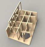
How do you assure there're proper amount of glue (and pressure during drying) on all those contacting surfaces of interlocks? (and you got plenty of them)
I've done only one lock and just relied on excessive glue for the bonding, very crudely I guess that's not good enough for all those (preciesely cut) interlocks.
How do you assure there're proper amount of glue (and pressure during drying) on all those contacting surfaces of interlocks? (and you got plenty of them)
I've done only one lock and just relied on excessive glue for the bonding, very crudely
I guess that's not good enough for all those (preciesely cut) interlocks.Hi CLS
Only a small amount of glue required on any joint really. By the time you clamped it together(or interlocking like this is self clamping) tight any more than that will only end up squeezing out.
I normally apply a thin bead along the joint and then evenly spread this around the contact area with my finger. This method seems to have the least mess for me yet still ensures good air tight contact.
If in doubt using more than necessary is better than too little when it comes to air tight cabinets.
Damn this CNC machine. With the options it opens up I've felt compelled to go back and rethink the Aurora. I'm working to give it a make-over including reworking the bracing in similar way as shown a few post ago.
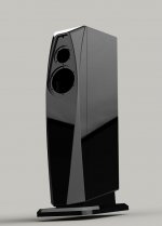
Before that however I wanted to take a look at the baffle. CNC allows for more complex shapes so I went ahead and adjusted the facets to a more sweeping feature that follows a similar profile to the original shape and added large radius's to the previously sharp edges. Diffraction should be reduced even further.
Here's the first iteration of the baffle which I really like.
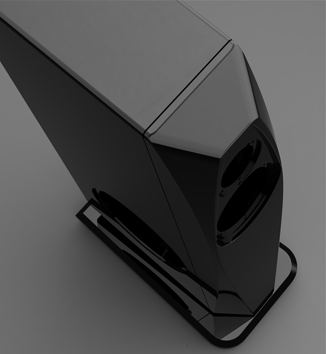
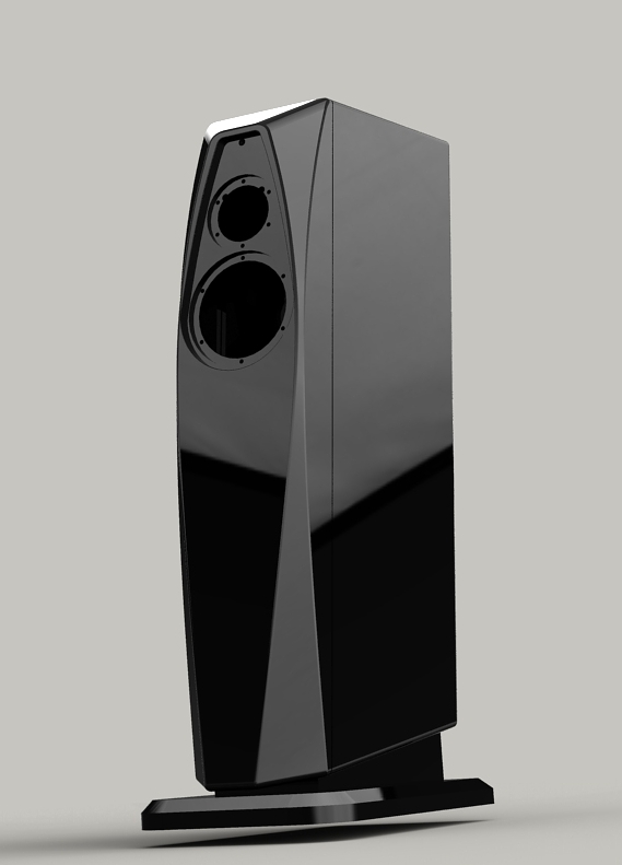
A bit more tweaking and that'll be another job done.
The larger Apollo will remain in the more angular style for this build.
Before that however I wanted to take a look at the baffle. CNC allows for more complex shapes so I went ahead and adjusted the facets to a more sweeping feature that follows a similar profile to the original shape and added large radius's to the previously sharp edges. Diffraction should be reduced even further.
Here's the first iteration of the baffle which I really like.
A bit more tweaking and that'll be another job done.
The larger Apollo will remain in the more angular style for this build.
Attachments
Damn this CNC machine. With the options it opens up I've felt compelled to go back and rethink the Aurora.
Hi Shin,
Your speakers show an amazing combination of beauty, function and style.
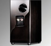
Do you plan to use a sealed bass cabinet or also offer ported options?
My last speakers used a lower front baffle MLTL port with very good results, but a 4" hole is ugly. A bottom port location would have more style and might integrate with your design theme. Rear ports allow more style flexibility, but I have found rear wall placement complications.
Attachments
Member
Joined 2009


If in doubt using more than necessary is better than too little when it comes to air tight cabinets.
Especially with thirsty MDF edges. I pre-treat them with a bead of woodglue, and let that set, rubbed in with the finger, before I use glue on the joint.
I wonder to ask You for Yours opinion, will the type of drivers You chose also be suitable for the max. natural sound playback possible ? if this parameter would be the main criteria ?
Hi Soundrays
That's a tough question to answer because there's no correct reply. Much of the sound your drivers reproduce will be influenced by a combination of the crossover, cabinet construction and room acoustic. These are unknown variables to me but if I had to give a broad generalisation then I can say I really like what RAAL, Audiotechnology and Scanspeak Revelator drivers do. Seas prestige range is a great choice too with gems such as the CA22RNY, ER15RLY and 22TAF/G. I've had these drivers in hand for awhile now and I'm extremely impressed for the money.
Hi,
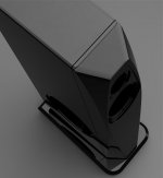
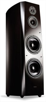
I like the sharp edges and more triangulated facets a lot more. It makes a much bolder statement as design.
This more sweeping design, in my humble eyes, bears parallels with the Dell/Alienware PC's.....
If you persue this more rounded design: what about replacing the straight edge above the tweeter with a rounded one following the radius of the tweeter....the narrow portion of the baffle becomes an elipse which might fit better to the overall design.
Huib
Thanks for the input.
I too like the angular look, its something I've done for years now but with more tools at my disposal I want to take advantage of the possibility to improve the sound further with more complex cabinet construction and baffle shapes that I didn't have the facilities for previously.
I too like the angular look, its something I've done for years now but with more tools at my disposal I want to take advantage of the possibility to improve the sound further with more complex cabinet construction and baffle shapes that I didn't have the facilities for previously.
Damn this CNC machine. With the options it opens up I've felt compelled to go back and rethink the Aurora. I'm working to give it a make-over including reworking the bracing in similar way as shown a few post ago.
How many axis CNC machine do you have? the kind of curves you've done would require 4 or maybe 5 axis.
Curves on the baffle look much better though.
How many axis CNC machine do you have? the kind of curves you've done would require 4 or maybe 5 axis.
Curves on the baffle look much better though.
Just to clarify: 4 axis is usually a 3 axis machine + lathe.
Yes a 5 axis would make quick work of what I have here but its all possible on a 3 axis too although will take considerably longer to machine. I expect about 5-6 hours machine time per baffle with a bit change at some point throughout the process.
For anyone interested here's a couple of youtube videos of guitar bodies being machined on 3 axis and whilst they're not loudspeaker baffles you can see how the machining would translate:
DBZ Guitars - Bolero - CNC Time Lapse - YouTube
DVD Volume 2: CNC Guitar Machining - YouTube
To speed things up I may machine an acrylic mold and then use a two part resin but this needs some more investigation.
Well actually if there is one thing I would have criticized the old design for is regarding to the baffle. I don't have any experience with this myself but many designers (I can probably quote Lynn Olson and Dr. Geddes) are pointing to the the fact that sharp edges around the source actually means diffraction sources. So I'm all about rounding everything near a driver.
The thing is that your second design also isn't a low diffraction one, the radius just isn't large enough.
The thing is that your second design also isn't a low diffraction one, the radius just isn't large enough.
Well actually if there is one thing I would have criticized the old design for is regarding to the baffle. I don't have any experience with this myself but many designers (I can probably quote Lynn Olson and Dr. Geddes) are pointing to the the fact that sharp edges around the source actually means diffraction sources. So I'm all about rounding everything near a driver.
The thing is that your second design also isn't a low diffraction one, the radius just isn't large enough.
Hi Sunra
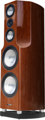
A basic baffle is often a rectangle and even though the angular one had edges at facets it had a step up over those in this regard because it was non square. This also led to minimising the width of the baffle around the drivers so it strived to adhere to the minimum baffle width philosophy.
Re: the radius. These are between 5-30mm depending on where your looking but your correct, the design isn't intended to eliminate diffraction. Its designed to reduce them over what you see from the more common baffle designs. If the goal is almost zero diffraction then a sphere would be a good starting point but that brings about its own problems too. As always its about balancing the variables within the constraints of a design brief.
How many axis CNC machine do you have? the kind of curves you've done would require 4 or maybe 5 axis.
Curves on the baffle look much better though.
As Shin already said, 3 axis is fine for what he is doing. 4 axis would gain nothing, and even 5 axis would probably not be any faster due to the surface needing to be ball nosed regardless.
OT: Is that VH-HET in your avatar?
After months of searching and procrastinating I've got off the fence and ordered a CNC machine
Its 3 axis with a 1220mm x 1220mm working area which is great for 4ft x 4ft sheets. It'll handle all types of wood and plastics. With a slower feed rate and the water cooling attachment it'll also do marble/corian and softer grades of alu. I saw the same machine working with a plasma cutter attachment and I plan to get one of those eventually to make working metals a simpler task.
Should arrive first week of next month and I have to say I'm looking forward to the extra level of design flexibility it will offer - I plan to go back and redo the bracing with channel rebates and now make them interlocking.
I'll be sure to post a photo at that point and maybe a video or two of it in action cutting the parts for the Apollo.
Hi Shin, long time no see. But I can see that you are busy at work and your new designs are fantastic. The CNC router or mill will give you lots of options. Two methods that I always wanted to try for cabinet construction are a mineral or sand and glass fiber filled epoxy front baffle. This would be perfect for the CNC application although it would be hard on tools. The beauty of this method is that you can pour the mineral filled epoxy into a mold that is very close to the final form then machine it to tolerance. So you don't have to remove all that much material.
The other method involves making an extremely rigid and dead side and back wall out of two layers of high grade plywood and either short cut pieces of cardboard tubing or aluminum tubing. With this idea it is kind of like large honeycomb panels. So you would need to machine small round grooves in the panel to create a kind of honeycomb patterning. Then glue maybe 3/4 inch pieces of 1 or 2 inch tubing into the routed grooves. Then bond the panels together with maybe a 1/2 inch spacing. Then leave one side open for sand fill. I think this could work well for large speaker enclosures.
- Status
- This old topic is closed. If you want to reopen this topic, contact a moderator using the "Report Post" button.
- Home
- Loudspeakers
- Multi-Way
- Apollo Construction Diary