I specifically said I was presenting (and looking for feedback on) a potential way of easily and accurately measuring acoustic centre offset of two drivers, besides the usual impulse method which isn't too reliable or accurate in practice.
If you want the most accourate method, first you need to measure synchronised impulse responses of the two drivers, then calculate wavelet transform of the impulse responses, and then calculate cross correlation between them. No need for thanks

- Elias
Okay, I'll plead guilty to dragging the topic off into phase allignment through the crossover region that you clearly (on re-reading your initial topic) weren't asking about. I assumed that the ultimate goal of good crossover stitching had to be the eventual goal. If not, then what is the goal?
If you want inter-unit delay then how about measured group delay, that you seem to have, and looking for the approximate delay in the center of each driver's band, or more accurately the comparison of measured phase to minimum phase (as suggested by nearly everyone).
Out of curiosity, what will you do with the info when you have it?
David
I understand this, however the original point of the thread was "how to measure acoustic centre offset" not "how to design a crossover that phase tracks". Related things sure, but not one and the same.As you know group delay and phase response are related, but if we are talking about system construction from multiple parts then the phase allignment through the crossover region is the primary concern. Group delay considerations won't guarantee this.
With proper crossover design both time aligned and non-time aligned designs can phase track through the crossover region. As I said in my previous post, they're really orthogonal issues.
Yes, part of the problem with trying to measure absolute phase of two different drivers in two separate measurements as keyser was describing. You can see if they phase track (to the nearest 360 degree cycle) but can't determine absolute offsets. By measuring both drivers at once through their crossovers, the problem of absolute reference and having to track back to 0 Hertz is avoided.Two units will have the same group delay if they have the same slope of phase curve. This really needs to be viewed in a linear frequency scale rather than the usual log scale. Also, a phase curve only implies a particular delay if it is linear and tracks back to 0 degrees at 0 Hertz.
Because some of the phase shift is amplitude response related, we measure excess phase instead of phase, this allows us to see only that which comes from the time delay and the all-pass response of the crossover. Now time alignment means the middle of each drivers bandwidth should have the same excess phase slope, and an easier way to see that on a graph is the excess group delay which is the derivative. Or have I missed something ?
Again, you're looking at it from the angle of phase tracking for the purpose of correct amplitude summing, the original question is how to measure the acoustic centre offset. Of course in any properly realised design you would want to take the additional step of ensuring phase tracking through the overlap region too. I'm not arguing against this.Even then two curves can have a constant phase span between them (one won't track back to 0 at 0) and they will not add in phase. for this reason I would always rely on phase curves rather than group delay curves. It shows you what you really need to know.
As have I, which is what prompted me to find a simpler and more reliable approach.I have played with time allignment via impulse response and also find it unreliable.
Do we only care about phase tracking through the crossover region though ? If you're only concerned about amplitude summing on axis then the answer is probably yes, but that's not the only consideration.For the most part it tells you about mid band time delay for each unit, when you again only care about phase through the regions of overlap. You can time allign two units (in the middle of their bands) and still have poor phase overlap in the crossover region, leading to poor combined frequency response.
I sense a bit of deja vu as we've debated the same point in a couple of other threads and it wasn't really my intention to reignite that line of discussion here, but since so many replies have already gone this way its too late to pull it back I suppose.
Suffice to say that high or low frequencies arriving first must surely be audible (perhaps subtly) if the group delay is sufficient, although I'm sure in practice the required delay is pretty large compared to what you might find on a typical non-stepped baffle with small dynamic drivers. (Horns mixed with dynamic drivers might have depth differentials great enough to be bordering on trouble though)
Other factors are incorrect tracking of inverse square law fall-off of each driver if one is closer to the listener than the other, and variations of acoustic centre error as you go off the horizontal axis. (Could be either beneficial or detrimental for phase tracking depending on the driver off-axis characteristics and crossover type)
Whether any of these things matter or not is a matter of scale - how much error are we talking about. If the error in offset is small relative to the crossover frequency its probably not an issue. If the acoustic centre error is large, it may be an issue.
I know you believe phase tracking alone is enough but answer me this, if you were faced with two drivers whose difference in depth mounted flat was more than a wavelength at the crossover frequency, would you still consider it acceptable to simply bend the phase response of the filters to give phase tracking ? Or is there a point at which you would say "this offset is just too much to work with".
Last edited:
No.Presuming that they could be generated and recorded properly, are the restitution of square waves a good witness for this ?
Time alignment of driver acoustic centres alone won't give good square wave reproduction. You also need a completely linear phase summed response. (Phase shift only due to measurement path distance)
I'm no expert on filters, but I believe that of analogue filters, only 1st order high/low pass will sum to a linear phase result.
Not that it matters, everything I've read says that ability to reproduce a square wave is not an important or audible criteria for a speaker, certainly on non-artificial signals like music.
BW1 sums to minimum-phase not linear phase. Only a DSP system is capable of linear phase.I'm no expert on filters, but I believe that of analogue filters, only 1st order high/low pass will sum to a linear phase result.
Even for a linear phase system on the design axis, move off-axis much and the result is no longer linear phase.
Dave
So accurate square wave reproduction (within the limits of the total bandwidth of the speaker) is impossible with a passive design ?BW1 sums to minimum-phase not linear phase. Only a DSP system is capable of linear phase.
That's not to say that you can't reasonably good square wave results with them, that's how Dunlavy used to do to promote his systems. It has some overshoot and settling on step response, but that's going to happen with any non-DSP system due to the inherent low-pass nature of any speaker system, disregarding the highpass.So accurate square wave reproduction (within the limits of the total bandwidth of the speaker) is impossible with a passive design ?
The issue still is that even within the bandpass of the system, the bandpass nature outside of what one considers the bandpass still has influence on the phase within the bandpass.
It may be that the BW1 of the non-DSP systems has the best group-delay system response, I'm not sure of that. There are a couple of what are called transient-perfect passive systems, but not necessary very practical. John K had a good set of papers covering this at his old site. I don't recall if he has them at his current Music and Design pages.
Dave
I'm rather bemused by this suggestion - how exactly is taking multiple independent measurements of drivers and constructing a 3D CAD model of the physical shape of the drivers more straightforward than a single measurement taken with a microphone ?I'm a bit puzzled by attempts to measure acoustic offset (the OP) in various ways when there is a simple, straightforward way to do it that can be very precise. It does require taking the measurements and creating a reasonably accurate model of drivers and system (3-d space location of drivers and mic) in design software,
I read the linked paper and it seems a rather complicated and indirect way of trying to measure it.
Can you describe what they are exactly ? I'm assuming that the biggest potential problem is insufficient driver bandwidth beyond the crossover frequency, or insufficient spacing between crossover points in a 3+ way system.Trying to use excess group delay has several issues that make it less than an accurate method.
The group delay might be non-linear due to imperfections in the amplitude response, but a single, conventional cone driver has very flat excess group delay in it's passband right up to very high frequencies where there may be a slight increase in excess group delay (relative to mid frequencies) due to shrinking effective cone area moving the effective acoustic centre back. The effect is very minimal on most drivers though, in the order of just a few mm equivalent distance or less.It is not possible to measure the acoustic offset between two drivers unless a specific frequency is given where the measurement should be fullfilled, because both drivers are having nonlinear group delay since they are fundamentally causal.
Try measuring excess group delay of a few drivers and you'll see.
Last edited:
I think you've misunderstood my statement. The measurements are taken at the same with the same mic position. The 3-d part is to create a speaker system model with the correct relationship of drivers as mounted on a baffle and the placement of the mic, that's all. The z-offset is then determined to adjust for the relative acoustic offset between drivers on the z-axis. Determining the 2-d placement on the baffle is simple. This accounts for the excess-delay due to the vertical and lateral horizontal offsets. The only unknown is the relative offset between the drivers on the z-axis.I'm rather bemused by this suggestion - how exactly is taking multiple independent measurements of drivers and constructing a 3D CAD model of the physical shape of the drivers more straightforward than a single measurement taken with a microphone ?
It's direct. The measured summed response inherently includes all excess-delay.I read the linked paper and it seems a rather complicated and indirect way of trying to measure it.
Remember, what you're doing at this point is not related to any crossover, what you want is an accurate starting point. That is, measure both drivers individually, measure the summed response of both together, then enter all three into a software design package. The crossover work comes afterwards. Any limitations of drivers in the stop-band due to driver bandwidth is a separate issue. That has more to do with making the choice of which drivers to use prior to making any measurements of drivers on the baffle.Can you describe what they are exactly ? I'm assuming that the biggest potential problem is insufficient driver bandwidth beyond the crossover frequency, or insufficient spacing between crossover points in a 3+ way system.
I should point out the the driver models created are minimum-phase, using HBT phase generated from the FR model made from the measurements.
Dave
Last edited:
.DBmandrake said:I specifically said I was presenting (and looking for feedback on) a potential way of easily and accurately measuring acoustic centre offset of two drivers, besides the usual impulse method which isn't too reliable or accurate in practice.
I wasn't really looking for a debate on whether acoustic centre alignment actually matters or not, nor was I looking for a way to measure or design the phase tracking of a crossover.
Acoustic centre alignment and phase tracking are related but orthogonal problems. You can have acoustic centre alignment without phase tracking, you can have phase tracking (through the overlap region at least) without acoustic centre alignment, and you can have both (or neither!) at once.
Some people think acoustic centre misalignment doesn't matter, that's fine, however I'm still interested in ways of measuring it
AS Elias suggested, re-worded, the problem is the driver has it’s own phase response and if you look with a time ruler, unless at zero, you see that represents a time delay that changes with frequency.
If you consider it as Richard Heyser did, it is as if the physical depth location of the source changes with frequency.
Thus, if you ask “where is even a single driver in time” the answer depends on the frequency and phase response as well as the total fixed time delay.
A large heavy subwoofer driver, may have an inherent time delay equating to a foot or more, any low pass filter also adds time delay (all filters add delay the low past more so).
In that case, it may be more intuitive to examine the phase response of the system as built and then ascertain the possible different location in the crossover region. Here, a conventional GD plot shows the spread in time relative to the shortest fixed delay.
I would disagree with that.You can have acoustic centre alignment without phase tracking, you can have phase tracking (through the overlap region at least) without acoustic centre alignment, and you can have both (or neither!) at once.
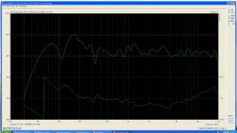
Here is an old SH-50 speaker that has crossovers around 400Hz and around 1200Hz, it was measured in place in my living room with a motorcycle and secretary desk in very close proximity (6 inches) from the mouth and a wall 3 feet away.
This is at 1 meter in room, no eq, passive xover and with as one can see, there is no phase rotation like one would expect from a forth order xover used on the hf for example. It is the same dusty speaker, same location I posted to with the square waves it produced.
The close acoustic spacing (less than ¼ wl) allows drivers to add coherently into one source within the horn, as the high frequencies emerge from a crossover first, they go to the rearmost driver. AS the wave progresses forward from the small end, at a region where the horn expansion rate is suitable for mid range, those frequency components are added in time as they emerge from the xover next, same for the lower frequencies and so on in a four way system. What emerges is a portion of a spherical wavefront “as if” it came from a single wide band driver on a large CD horn and so this is the response across the horns pattern, not limited to one exact spot like when drivers are farther apart..
Best,
Tom
Attachments
Last edited by a moderator:
The problem with measuring the drivers individually is you're back to requiring dual channel measurements to ensure cycle accurate time delay between the two measurements, otherwise the phase is in doubt.Remember, what you're doing at this point is not related to any crossover, what you want is an accurate starting point. That is, measure both drivers individually, measure the summed response of both together, then enter all three into a software design package. The crossover work comes afterwards. Any limitations of drivers in the stop-band due to driver bandwidth is a separate issue. That has more to do with making the choice of which drivers to use prior to making any measurements of drivers on the baffle.
However if you want to measure the two drivers independently like this, raw, no crossovers, my method can be adapted to that as well, provided dual channel mode is used. (Perhaps keyser might like to try this to see what results he gets ? I'm not currently set up for dual channel measurements)
Start with a windowed impulse measurement for the most forward driver, switch to the excess group delay measurement, locate the bottom of what should (without a crossover) be a fairly broad and flat excess group delay, adjust the delay time for phase estimation until the excess group delay at the cursor is equal to zero.
Then take a second measurement, being careful to leave the start and end markers alone (Configured in File->Options) and leave the delay time for phase estimation alone, go to the excess group delay measurement, locate the bottom of what again should be a very flat excess group delay, and the delay time can be read directly from the screen at the bottom left, and offset calculated from that.
Does that address your concerns ?
If starting from scratch with two drivers and no crossover this may be a better approach, while the first approach is still useful for measuring existing speakers without dismantling them.
Last edited:
I understand variations in the amplitude response of the individual driver will cause group delay that will move the apparent acoustic centre about, however that's not really the issue.AS Elias suggested, re-worded, the problem is the driver has it’s own phase response and if you look with a time ruler, unless at zero, you see that represents a time delay that changes with frequency.
If you consider it as Richard Heyser did, it is as if the physical depth location of the source changes with frequency.
Thus, if you ask “where is even a single driver in time” the answer depends on the frequency and phase response as well as the total fixed time delay.
The group delay that is due to the minimum phase part of the drivers response will be corrected by any equalisation curve in the network for that driver which corrects the response error.
So if your driver had a peak in its response and attendant group delay, equalising that peak in the response in the network will also correct the group delay error. The flatter the equalised frequency response of the individual driver the flatter the group delay will be.
What is left over after that is the group delay due to the distance offset. Assuming a relatively flat amplitude response its the time delay from acoustic centres that still sets the baseline group delay difference between the two drivers, and is the part that can only be corrected with physical offset. (Or a pure delay)
Last edited:
Simon,
I may have missed something in previous posts, but why on earth would you measure drivers+x/over?
Filter design starts with measuring raw drivers in-box, then measured results are then imported into a filter design package. Any Calsod/Leap/Lspcad/SE/Boxsim etcetc. toturial will tell you in detail how this is done.
From some private communications -around 1994-with Wittold Waldman, the CALSOD designer, it appeared that with a single point (do not touch/move the box and mic) it is not even neccessary to manipulate the measurement files. DLR, I think however, has a slightly different view.
So from a system design point of view, I fail to see why one would measure drivers connected to an existing x/over, unless, of course, this is a strictly academic exercise.
Kind Regards,
Eelco
Yes, you did miss something - the thread was not originally about crossover design, only about ways to measure acoustic centre offset, nowhere in my original post did I mention it as a part of a crossover design process, or make any assumptions that the measurement would only be made on raw drivers before a design was started.Simon,
I may have missed something in previous posts, but why on earth would you measure drivers+x/over?
Filter design starts with measuring raw drivers in-box, then measured results are then imported into a filter design package. Any Calsod/Leap/Lspcad/SE/Boxsim etcetc. toturial will tell you in detail how this is done.
[...]
So from a system design point of view, I fail to see why one would measure drivers connected to an existing x/over, unless, of course, this is a strictly academic exercise.
In fact one of my goals was to be able to measure the acoustic offset in any existing design with a single measurement without disassembly of the speaker or crossover/wiring, and I'm not aware of any other approaches which will do this with any degree of accuracy.
As dlr has pointed out, measuring the drivers separately is probably more accurate, whether by a significant amount I don't know, as I was getting pretty good results with my initial method.
So yes, measuring it on an already completed speaker is largely an academic exercise.
Last edited:
Measuring an existing finished speaker is, yes. Not if its a work in progress.OK, so it is largely academic.
The relative acoustic centre offset depth of the two drivers ?But then again, just for the sake of curiosity, what do you learn from it?
Not sure what you're getting at there.
Right;DBMandrake said:The group delay that is due to the minimum phase part of the drivers response will be corrected by any equalisation curve in the network for that driver which corrects the response error.
Yep;So if your driver had a peak in its response and attendant group delay, equalising that peak in the response in the network will also correct the group delay error. The flatter the equalised frequency response of the individual driver the flatter the group delay will be.
What is left over after that is the group delay due to the distance offset. Assuming a relatively flat amplitude response its the time delay from acoustic centres that still sets the baseline group delay difference between the two drivers, and is the part that can only be corrected with physical offset. (Or a pure delay)
That is exactly how the square waves I linked were produced, in the case of an SH-50, it is a passive crossover network and the progressive delays imposed by the driver mounting locations on the horn shape exactly counter the time delays imposed by the mid/low and mid/high crossovers.
While normal crossovers have a step in the group delay caused by the shape and amount of phase rotation (going from well above to well below xover) which puts the high frequency ahead of the low frequency range, it is possible to eliminate that as well.
With DSP that is easy but it can be done passively also, examine the phase response for the sh-50 I posted a couple back.
That is the actual measured phase (at a meter in a cluttered living room) not with excess phase removed, that looks like one driver not 7..
I am not sure I understood the original goal however.
With a TEF machine, one would measure the ETC for whichever one was closer or had the higher cutoff.
This positively identifies the time of the first arrival and that value is automatically removed when you measure the magnitude and phase.
For what I think was the goal here, one would set the time (based on the closest / highest ) and then go ahead and measure both speakers.
This captures the phase difference between the two speakers and if you know the frequency and phase, you can calculate the time difference between them at any frequency of your choosing.
Alternately, one could make an imaginary model of the response and get the minimum phase part, one could estimate the radiator center, the voice coil equivalent circuit and model that because part of the delay is the low pass effect of the inductive roll off. All that is arm waving compared to measuring the actual drivers though.
Best,
Tom Danley
Danley Sound Labs
Last edited by a moderator:
Actually, no. One thing that I was not aware of when I wrote the article is that it is not necessary to measure phase at all for this procedure to work. This is probably not an intuitive idea, but the fact is that the only requirement is accurate SPL measurements. Period. I came up with this when using the LMS measurement system. LMS does not measure phase, it measures by using stepped sines. The user is supposed to "tail" the measurements, then generate phase, but I was using CALSOD that will also generate phase.The problem with measuring the drivers individually is you're back to requiring dual channel measurements to ensure cycle accurate time delay between the two measurements, otherwise the phase is in doubt.
The only phase needed for the procedure is the HBT generated phase of the two individual raw driver measurements. When the summed response created from the models has the correct excess-phase (acoustic offset) included, the result will match the measured summed response.
A dual channel mode system is not required. It is preferred, since that type of system eliminates the errors introduced in all upstream components, preamp, amp, cables, resistance in the speaker wire, whatever. But phase need not be measured.However if you want to measure the two drivers independently like this, raw, no crossovers, my method can be adapted to that as well, provided dual channel mode is used. (Perhaps keyser might like to try this to see what results he gets ? I'm not currently set up for dual channel measurements)
Dave
- Status
- This old topic is closed. If you want to reopen this topic, contact a moderator using the "Report Post" button.
- Home
- Loudspeakers
- Multi-Way
- Measuring driver acoustic offset using excess group delay ?