Hello !
This thread is dedicated for discussion of methods of generating stereo sound in a small room acoustic space by using a single DIY loudspeaker !
Encouraged by the results achieved in the Stereolith thread I explored the concept of single speaker stereo further:
http://elias.altervista.org/html/SingleSpeakerStereo.html
The general principle I'm using is this:
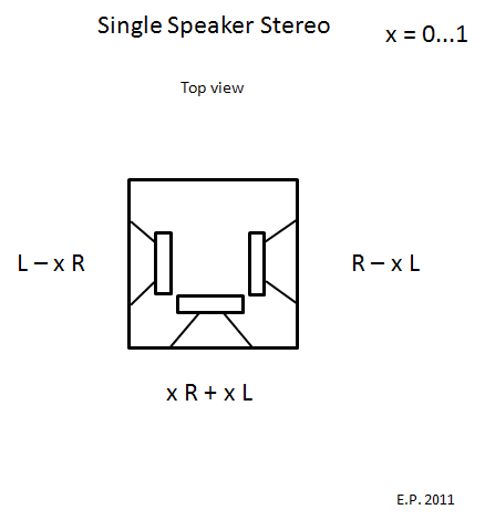
Interesting is the selection of parameter x !
When x = 0, the speaker is bipolar sideways projection (Stereolith).
When x = 1, the speaker is MS stereo.
I think the optimal value is about x = 0.5, which I'm using at the moment.
The Cardboard is back, but now totally different since enhanced with psychoacoustic vector steering !
I've been listening to this for about a week now, and results are very positive ! There is a great potential !
Experimenting recommended !")
*************
EDIT 2017:
Dropbox has deceived their customers and eliminated public folders. Thus the pictures linked herein are not visible any longer.
Go to http://elias.altervista.org/html/SingleSpeakerStereo.html to see the pictures
- Elias
This thread is dedicated for discussion of methods of generating stereo sound in a small room acoustic space by using a single DIY loudspeaker !
Encouraged by the results achieved in the Stereolith thread I explored the concept of single speaker stereo further:
http://elias.altervista.org/html/SingleSpeakerStereo.html
The general principle I'm using is this:
Interesting is the selection of parameter x !
When x = 0, the speaker is bipolar sideways projection (Stereolith).
When x = 1, the speaker is MS stereo.
I think the optimal value is about x = 0.5, which I'm using at the moment.
The Cardboard is back, but now totally different since enhanced with psychoacoustic vector steering !
I've been listening to this for about a week now, and results are very positive ! There is a great potential !
Experimenting recommended !
*************
EDIT 2017:
Dropbox has deceived their customers and eliminated public folders. Thus the pictures linked herein are not visible any longer.
Go to http://elias.altervista.org/html/SingleSpeakerStereo.html to see the pictures
- Elias
Last edited:
It will never work as well as two separate speakers.
rgds, sreten.
why never?
Amazing ! It will never work

Luckily I didn't know that because for me this works much better than conventional stereo triangle !
Why ? Because this circumvents many artefacts related of conventional two speaker reproduction.
- Elias
This is not a single loudspeaker.
This is three loudspeakers in one enclosure.
This has been done for decades.
could You post any links please?
Elias,Hello !
This thread is dedicated for discussion of methods of generating stereo sound in a small room acoustic space by using a single DIY loudspeaker !
Encouraged by the results achieved in the Stereolith thread I explored the concept of single speaker stereo further:
Elias Pekonen Home Page - Stereophonic Sound from a Single Speaker
The general principle I'm using is this:
An externally hosted image should be here but it was not working when we last tested it.
Interesting is the selection of parameter x !
When x = 0, the speaker is bipolar sideways projection (Stereolith).
When x = 1, the speaker is MS stereo.
I think the optimal value is about x = 0.5, which I'm using at the moment.
The Cardboard is back, but now totally different since enhanced with psychoacoustic vector steering !
I've been listening to this for about a week now, and results are very positive ! There is a great potential !
Experimenting recommended !
- Elias
You are generating stereo sound with three discreet loudspeakers that happen to be in a single box, not "Stereophonic Sound from a Single Loudspeaker".
What is "parameter x", and how is "parameter x" varied between 0 and 1 ?
A wiring diagram would be helpful for others to do the recommended experimenting ...
I think the optimal value is about x = 0.5, which I'm using at the moment.
Now we're talking
How did you implement the rematrixing?This is not a single loudspeaker.

It's a multi element single loudspeaker !
- Elias
Elias,
What is "parameter x", and how is "parameter x" varied between 0 and 1 ?
A wiring diagram would be helpful for others to do the recommended experimenting ...
The x is a gain factor, x = 0 means no signal (for given input) and x = 1 means signal is passed unmodified.
If x is to be made continously variable, it may be best done using active circuit or controller for example Behringer DCX or similar.
However, x = 0.5 can be done passively !
This schematic allows comparison between x = 0 (Stereolith) and x = 0.5 (vector steering) by a single switch ! (x = 0 means switch is closed)
An externally hosted image should be here but it was not working when we last tested it.
Using the switch while listening is enlightening !
- Elias
Hi Elias,
Something more complex for ya... Works well for me. Slight variation to yours is i angled the left / right speakers about 30deg forward.... Not sure if this matters as i did this from the start without to much thought.
Below is my simple version.
My enhanced version splits s0,s1 into above 5k and below 5k frequency ranges with a 6db per octave hp/lp. Different degree setting to angle (35.26) below 5k and angle (54.74) above 5k. It also delays OutCC.
Simple Version......
s0 = left input
s1 = right input
width = 0.5 to 1
degree = 35.26 * 0.017453; 1st number is angle.
OutL = (0.5*sin(degree))*(s0+s1)+0.5*width*(s0-s1);
OutR = (0.5*sin(degree))*(s0+s1)-0.5*width*(s0-s1);
OutCC = (0.70710678*cos(degree))*(s0+s1);
I do this in dsp.... You can do this with opamps etc... Just dont know how
btw the above keeps equal power to all 3 speakers (Very close to it) i.e L + R = L + C + R
Cheers
Optic
This is somewhat like a stereo microphone with sum and difference processing. You can use it to vary the pattern and send left and right energy off in their respective directions to varying degrees. The question is whether energy to the left and energy to the right is effective stereo. Perhaps with left and right reflecting surfaces it might be. Without reflections to create a physical separation I don't think it is.
Look up the Jensen precedents. They had a sum and difference system in a single cabinet.
David S.
Look up the Jensen precedents. They had a sum and difference system in a single cabinet.
David S.
That looks familiar.
http://www.diyaudio.com/forums/mult...channels-out-stereo-signal-3.html#post2686501
The 'only' difference is I use it on 3 separate DML panels. I may (soon) try it on a single panel, as the descriptions mentioned in the thread of Bessel array:
http://www.diyaudio.com/forums/multi-way/126045-bessel-array-2.html#post2773595
Last edited:
This is somewhat like a stereo microphone with sum and difference processing. You can use it to vary the pattern and send left and right energy off in their respective directions to varying degrees. The question is whether energy to the left and energy to the right is effective stereo. Perhaps with left and right reflecting surfaces it might be. Without reflections to create a physical separation I don't think it is.
Look up the Jensen precedents. They had a sum and difference system in a single cabinet.
David S.
Yes, reflectors to the left and the right are crucial, so is the level (and angle) of the resulting reflections.
I've sketched a prototype with larger full range drivers for L and R some time ago but haven't had the time to actually build it.
Hi Elias,
Something more complex for ya... Works well for me. Slight variation to yours is i angled the left / right speakers about 30deg forward.... Not sure if this matters as i did this from the start without to much thought.
Below is my simple version.
My enhanced version splits s0,s1 into above 5k and below 5k frequency ranges with a 6db per octave hp/lp. Different degree setting to angle (35.26) below 5k and angle (54.74) above 5k. It also delays OutCC.
Simple Version......
s0 = left input
s1 = right input
width = 0.5 to 1
degree = 35.26 * 0.017453; 1st number is angle.
OutL = (0.5*sin(degree))*(s0+s1)+0.5*width*(s0-s1);
OutR = (0.5*sin(degree))*(s0+s1)-0.5*width*(s0-s1);
OutCC = (0.70710678*cos(degree))*(s0+s1);
I do this in dsp.... You can do this with opamps etc... Just dont know how
btw the above keeps equal power to all 3 speakers (Very close to it) i.e L + R = L + C + R
Cheers
Optic
Those coefficients have so many decimals it must be based on academic research
Any references ? Gerzon ?So your three speakers, are they integrated as one, or spread in front in conventional triangle ?
- Elias
The question is whether energy to the left and energy to the right is effective stereo. Perhaps with left and right reflecting surfaces it might be. Without reflections to create a physical separation I don't think it is.
Sure, this kind of speaker must operate in harmony with the room ! It will not work in anechoic conditions. Also it may not work in arena or large auditorium, the side reflections may be too weak.
However normal living rooms have what it takes for this to work, relatively close side walls ! In my 25 m2 room it works very well ! This is a living room speaker
- Elias
have You considered/measured the effect of the back wave of one speaker superimposed on the output of other two speakers and of the output of each speaker diffracting around the box?
for me it looks like that for frequencies below about 700<1000 Hz the output from each of the speakers is equally all around just with little relative SPL differences plus small time delays
for me it looks like that for frequencies below about 700<1000 Hz the output from each of the speakers is equally all around just with little relative SPL differences plus small time delays
Yeah ! Now all you need to do is integrate your speakers as a single entity !
...
on a single panel, as the descriptions mentioned in the thread of Bessel array:
http://www.diyaudio.com/forums/multi-way/126045-bessel-array-2.html#post2773595
http://www.angelfire.com/sd/paulkemble/soundf.html
This is a same principle ! Elements B and D form a dipole for the difference signal, and elements A, C and E form a monopole for the sum signal. However, the reason for having three elements for the monopole is not immediately obvious, maybe it's just a forced fit into Bessel array format(?).
- Elias
This is a same principle ! Elements B and D form a dipole for the difference signal, and elements A, C and E form a monopole for the sum signal.
yes, looks the same
the wheel reinvented once again?
However, the reason for having three elements for the monopole is not immediately obvious, maybe it's just a forced fit into Bessel array format(?).
- Elias
it can be made purely by wiring this way, without even any passive filtering
- Home
- Loudspeakers
- Multi-Way
- Stereophonic Sound from a Single Loudspeaker