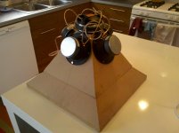
I've been dreaming of building a synergy horn (which I am well aware is different from a unity horn) ever since I heard the SH50. The Unity Horn is the closest I've come to finding a fully documented "multi-way horn" in the heritage of Tom Danley, so I thought I'd start there. If this is a success, I'll use what I learned to build a more proper Synergy horn. None of the original drivers are available, so I chose some budget drivers that seemed to fit the bill to minimize my losses. Alright, less talk - more sawdust.
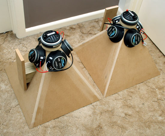
The mids are cheapo GRS 5SBM-8 5" sealed drivers (the grills pried off easily). The compression driver is the trusty Selenium D220Ti. I'm using a MiniDSP 2x4 for crossover. I'll probably crossover to one of the 15" pro drivers I have laying around. I'll worry about that later.
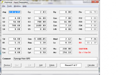
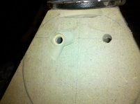
I've got the first horn built up and my measurement microphone calibrated. I built the unity horn as close to the original kit as possible from the information I've been able to gather. I did the port modification as documented here and tuned their length according to my Hornresp sim (0.95cm diameter, 0.5cm long). Measurements of the built horn put the throat-to-port length at about 8cm and port entry area at 56sq.cm.
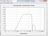
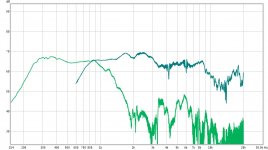
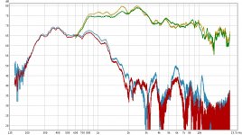
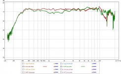
The results have been encouraging, showing that many parts of the midrange simulation are spot on (light green line). The low cutoff lines right up (300hz) and the notch from the first reflection apearts right where it should (1.9khz). However, the big difference is the roll-off in the mids beginning at 1khz. This where I'm looking for any advice. I've been going back through the sims trying to figure out what could cause such a steep roll-off. The one factor that comes to mind is if I miscalculated the diameter of the ports. Another possibility is a wrong-sized rear chamber.
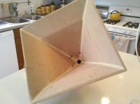
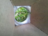
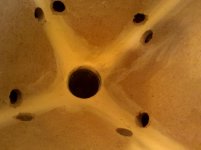
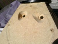
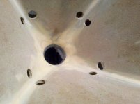
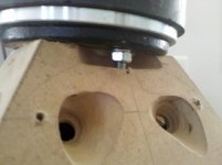
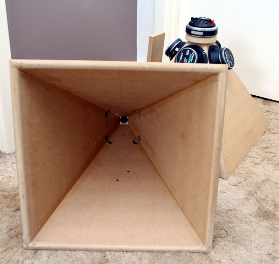
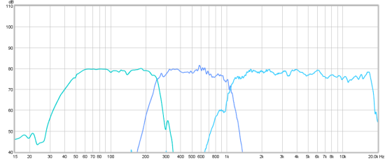
The compression driver looks promising as well (dark green line). The top end seems to break up earlier than I'd hoped (8khz). The real problem, though, is an irregularity in the off axis response. I setup a quick crossover and measured on axis (purple line) and 20 degrees off axis (gold line). The power response looks real good until you get to 5khz where there is a peak off axis. Any feedback here would be valuable as well. The compression driver was joined to the horn using this adapter. I dremeled off the threads and gorilla glued the remaining plate to the horn. The end of the wood horn is a 1.25" square and the diameter of the adapter plate is 1". I dremeled the adapter to make a conical transition from 1" to 1"25 and I filled in the corners where they meet, but I I didn't go crazy. Perhaps I need to make this transition smoother? The body of the second horn is built, but none of the ports are drilled. I could attach just the compression driver and see what the response is without the midrange ports.
I am having SO MUCH fun!
The mids are cheapo GRS 5SBM-8 5" sealed drivers (the grills pried off easily). The compression driver is the trusty Selenium D220Ti. I'm using a MiniDSP 2x4 for crossover. I'll probably crossover to one of the 15" pro drivers I have laying around. I'll worry about that later.
I've got the first horn built up and my measurement microphone calibrated. I built the unity horn as close to the original kit as possible from the information I've been able to gather. I did the port modification as documented here and tuned their length according to my Hornresp sim (0.95cm diameter, 0.5cm long). Measurements of the built horn put the throat-to-port length at about 8cm and port entry area at 56sq.cm.
The results have been encouraging, showing that many parts of the midrange simulation are spot on (light green line). The low cutoff lines right up (300hz) and the notch from the first reflection apearts right where it should (1.9khz). However, the big difference is the roll-off in the mids beginning at 1khz.
This where I'm looking for any advice. I've been going back through the sims trying to figure out what could cause such a steep roll-off. The one factor that comes to mind is if I miscalculated the diameter of the ports. Another possibility is a wrong-sized rear chamber.The compression driver looks promising as well (dark green line). The top end seems to break up earlier than I'd hoped (8khz). The real problem, though, is an irregularity in the off axis response. I setup a quick crossover and measured on axis (purple line) and 20 degrees off axis (gold line). The power response looks real good until you get to 5khz where there is a peak off axis. Any feedback here would be valuable as well. The compression driver was joined to the horn using this adapter. I dremeled off the threads and gorilla glued the remaining plate to the horn. The end of the wood horn is a 1.25" square and the diameter of the adapter plate is 1". I dremeled the adapter to make a conical transition from 1" to 1"25 and I filled in the corners where they meet, but I I didn't go crazy. Perhaps I need to make this transition smoother? The body of the second horn is built, but none of the ports are drilled. I could attach just the compression driver and see what the response is without the midrange ports.
I am having SO MUCH fun!
Attachments
-
 UnityV1 input.png57.5 KB · Views: 3,756
 -
 UnityV1 modeled.png33.1 KB · Views: 3,665
 -
 unityv1 mids and highs.jpg97.3 KB · Views: 3,655
 -
 IMG_20110904_172419.jpg403.9 KB · Views: 1,390
 -
 IMG_20110904_172305.jpg366.3 KB · Views: 3,671
 -
 unityv1 power response.jpg90.4 KB · Views: 3,634
 -
 IMG_20110824_211050.jpg965.9 KB · Views: 1,010
 -
 IMG_20110820_190614.jpg439.3 KB · Views: 1,019
 -
 IMG_20110904_172437.jpg414.6 KB · Views: 1,144
Last edited:
You ARE THE MAN, MAN! ) I am gathering information for the same project. Maybe we can help each other.
Now back to science. The CD entry hole does not look right to me. That part must be very very smooth with no rapid changes in flare. I think that you should try to move the cd further back th throat.
BDW. Can you explain to me what's the big diffrence between Synergy and Unity?
) I am gathering information for the same project. Maybe we can help each other. Now back to science. The CD entry hole does not look right to me. That part must be very very smooth with no rapid changes in flare. I think that you should try to move the cd further back th throat.
BDW. Can you explain to me what's the big diffrence between Synergy and Unity?
Now back to science. The CD entry hole does not look right to me. That part must be very very smooth with no rapid changes in flare. I think that you should try to move the cd further back th throat.
From what little i know about compression drivers and horns, I'd say you're right. The adapter has to make a very smooth transition between the round driver and the square horn throat.
Nice project!
About the mid rolloff;
If you read the akabak manual, it states that the trapped air in the mid chamber-midport forms an extra acoustic filter factor caused by the air molecules moving in a different way in a small volume (Vf in akabak), superimposed on the normal acoustic lowpass filter.
For this reason the acoustic lowpass filter formed by the midchamber-midport is lower in frecuency in reality than in your Hornresp sim, since Hornresp doesn't take this effect into account.
You can rather easily compensate for this by making your midchambers smaller by filling them up.
Succes!
Hi
I would follow the suggestions about a radius at the entry, one should avoid any straight cylindrical portions on the horn (as a hole bored through a plate is) unless it is very short in length.
You might look at a different compression driver that has a lower cutoff as in this design overlap is very desirable if you want to eliminate the crossover phase shift (like an SH-50) and have the result appear to be a single driver. Also, keep in mind that the exit wavefront on a compression driver is not always a plane wave, especially with larger format drivers. I have had very good luck with the BMS drivers which tend to have an expanding wavefront at their exit which makes the transition to the conical horn seamless..
The holes do form a “low pass” acoustic filter which is made of the mass of air in the port and the volume of air trapped under the cone body.
This is very desirable as it reduces the distortion the drivers produce.
The smaller the ports are, the lower the corner will be and also the less difference they make in the horn.
If you want to raise the mid corner F, then making the ports as short as possible (with a tapered or counter bore on the driver side) or increase the diameter is the easy path.
Have fun
Tom Danley
Danley Sound Labs
Danley Sound Labs, Inc. | Facebook
Wow, thank you all for some very constructive feedback. This is great.
This is the part of the construction I took the biggest guess at. From what I've found the original unity horn didn't have anything more than a thin adapter between the driver and horn and some sort of filler in the corners. my adapter is about 1/4" thick and I've beveled it to taper from a 1" diamter to 1.25". I seem to recall you mentioning that you used a 1" pipe to form the radius inside your unity prototype. My original concern was creating too narrow/gradual a transition and causing beaming at the highest frequencies. I'll use some more filler to make a smoother radius.
The BMS 4550 should be on the christmas list if I can get this arrangement to sound half decent. The nice thing is, when I decide to build a larger synergy horn I should be able to use the same mids and compression drivers.
It'll probably be at least a week until I have any updates (this week is going to be brutal at work). Also, It sounds like if I'm going to model these things correctly I'm going to have to bite the bullet and learn akabak
rvrazvan said:The rolloff at 1000 hz is normal and i dont think there is anything you can do about it. Except for using another driver maybe. The mid is in a bandpass enclosure. anyway..don't expect anything more than 2 octaves.
Looking at my measurements again, my midrange bandwidth is really from 250hz to 1000hz (two octaves). I'll continue to shorten my port length until I get 300hz-1200hz. If anybody knows where the acoustic crossover point of the original unity design occurs, I would be grateful.If you want to raise the mid corner F, then making the ports as short as possible (with a tapered or counter bore on the driver side) or increase the diameter is the easy path.
Hi
I would follow the suggestions about a radius at the entry, one should avoid any straight cylindrical portions on the horn (as a hole bored through a plate is) unless it is very short in length.
This is the part of the construction I took the biggest guess at. From what I've found the original unity horn didn't have anything more than a thin adapter between the driver and horn and some sort of filler in the corners. my adapter is about 1/4" thick and I've beveled it to taper from a 1" diamter to 1.25". I seem to recall you mentioning that you used a 1" pipe to form the radius inside your unity prototype. My original concern was creating too narrow/gradual a transition and causing beaming at the highest frequencies. I'll use some more filler to make a smoother radius.
You might look at a different compression driver that has a lower cutoff as in this design overlap is very desirable if you want to eliminate the crossover phase shift (like an SH-50) and have the result appear to be a single driver. A
lso, keep in mind that the exit wavefront on a compression driver is not always a plane wave, especially with larger format drivers. I have had very good luck with the BMS drivers which tend to have an expanding wavefront at their exit which makes the transition to the conical horn seamless..
The BMS 4550 should be on the christmas list if I can get this arrangement to sound half decent. The nice thing is, when I decide to build a larger synergy horn I should be able to use the same mids and compression drivers.
It'll probably be at least a week until I have any updates (this week is going to be brutal at work). Also, It sounds like if I'm going to model these things correctly I'm going to have to bite the bullet and learn akabak
I have had very good luck with the BMS drivers which tend to have an expanding wavefront at their exit which makes the transition to the conical horn seamless..
... which minimizes HOM?
Comments and mails
this is an e-mail containing information about unity horns
this thread that migh be usefull also:
http://www.diyaudio.com/forums/multi-way/88237-suitable-midrange-cone-bandpass-mid-unity-horn.html
this is an e-mail containing information about unity horns
this thread that migh be usefull also:
http://www.diyaudio.com/forums/multi-way/88237-suitable-midrange-cone-bandpass-mid-unity-horn.html
Comments and mails
this is an e-mail containing information about unity horns
this thread that migh be usefull also:
http://www.diyaudio.com/forums/multi-way/88237-suitable-midrange-cone-bandpass-mid-unity-horn.html
Thanks rvrazvan!
And as far as colaborating - that's why I came here in the first place! When looking at other completed multi-way-horn projects, I've been frustrated by the lack of documentation. Most of them are "look what I made" with just a few details as people ask for them. Although I may be learning as I go, it is my intention to document my blunderings and share as much as I can.
Ver.2 results
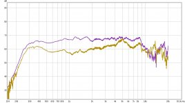
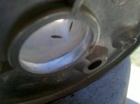
So I made some revisions. The Ports are now 3mm instead of 5mm. The throat transition is now very schmooooth. After seeing the measurements, I think I can safely carry the transition from the corners further down the horn without any fear of beaming if I choose. the results look pretty good! I also included a picture showing my compression driver mounting solution for anyone who cares to know.
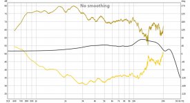
The measurement below shows the MF and HF drivers on and off axis. There are none of the dramatic off-axis anomalies as as there were before I smoothed the throat transition. I'm not sure whether to try more filler at the throat or move on. The Mids look great! I'd say they're totally usable. They are not as efficient as the HF driver, but I need to grab my SPL meter from work to calibrate my measurements.
So I made some revisions. The Ports are now 3mm instead of 5mm. The throat transition is now very schmooooth. After seeing the measurements, I think I can safely carry the transition from the corners further down the horn without any fear of beaming if I choose. the results look pretty good! I also included a picture showing my compression driver mounting solution for anyone who cares to know.
The measurement below shows the MF and HF drivers on and off axis. There are none of the dramatic off-axis anomalies as as there were before I smoothed the throat transition. I'm not sure whether to try more filler at the throat or move on. The Mids look great! I'd say they're totally usable. They are not as efficient as the HF driver, but I need to grab my SPL meter from work to calibrate my measurements.
Attachments
wow! U did good - here's one of Tom's early prototype for comparison w. MISCO mids - this is the coolest, most coherent and most practical horn arrangement ever made. HF driver = DE25
An externally hosted image should be here but it was not working when we last tested it.
Ver.2 x-over design
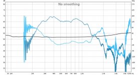
I guess it's no surprise, but the crossover is going to be tricky. Below are today's transfer function and phase measurements from the MF and HF drivers. Also included are the data files for anyone who'd like to play along.
I attempted and failed at making a crossover tonight before I ran out of daylight. I found it strange that even though the individual drivers exhibit constant directivity, when combined the crossover region exhibits a different response on and off axis. I had always assumed any "mistakes" in the crossover region would be constant directivity but that certainly isn't the case. Maybe once I nail the phase alignment this will go away.
Attachments
I'm not sure whether to try more filler at the throat or move on.
This was discussed at length on the old basslist. Don't have it saved, but IIRC the best results were with the transition extending to the mids vents, so experimenting with clay to find the optimum taper is what I'd do. From memory, it looks like you have a ways to go yet.
GM
Hi Greg,
I remember the Basslist discussion about the same way, and IIRC, a fair amount of time was spent getting the corner filleting right, along with the CD exit radius. I believe that Earl Geddes also ended up spending a fair amount of time on his waveguides doing that as well, but perhaps I'm overstating the amount of effort expended.
Best Regards,
Terry
Terry and GM recall the bass list, suggesting a trip to Mr Peabody’s wayback machine.
The Unity kit came about when Nick McKinney wanted to offer a DIY version of what we were selling for commercial sound.
After some arm twisting at work, we supplied Nick with the horn blanks, drivers and crossovers and he sold them from his company Lambda acoustics.
The issue of the corner fill came about when Nick did a much more thorough job filling the corners in than our production and as the hf and mids are tied together acoustically, the change in the corner fill detail caused the response enough to be different than the ones used at work and then required a new crossover based on his version of the real thing..
The approach jmorken shows on post 13 uses a later port refinement, like the Synergy horn.
Personally I would say you have enough fill and the corners look good but if you can open up the angle on the metal plate (back side in pic 2) you might get a slightly better result.
Also, since you are adding the outputs of two different ranges of drivers in a closed space and where the separation is acoustically small, having it all right is a key in how well it works.
If you eq’d what you already built to be flat with a hf droop like hifi speakers, you will probably like what you hear. If you got a compression driver that had a lower corner (hint like a bms 4550) your crossover will be easier / happier.
I don’t see a phase response but you should be able to make it flat at/near zero from about 400 to several Khz. When you don’t have crossover phase shift, you have a single source in time and over that frequency range, a square wave in makes a square wave come out.
Have fun
Tom Danley
Danley Sound Labs
Danley Sound Labs, Inc. | Facebook
Check this out guys!
Synergy coax horns
The mouth apparently is half a meter, so larger than standard Unity.
I've heard the original Unity twice and keen to hear Paul's build. Lives just 10min from me at Melbourne SE (or Australia's) "DIY Central"
Synergy coax horns
The mouth apparently is half a meter, so larger than standard Unity.
I've heard the original Unity twice and keen to hear Paul's build. Lives just 10min from me at Melbourne SE (or Australia's) "DIY Central"
- Status
- This old topic is closed. If you want to reopen this topic, contact a moderator using the "Report Post" button.
- Home
- Loudspeakers
- Multi-Way
- Unity Horn - budget drivers, active x-over