On a 2 woofer in parallel setup I wonder if there could be some benefits on using independent filters or just independent zobels.
Drivers are never fully identical and wires+connectors add R,C and L to the circuit...
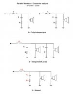
So, for a simple 1st order + zobel what do you think would be the best filter? (check pic)
On option 2 consider the zobel's are mounted close to each woofer and the inductor is on the back side of the speaker.
Drivers are never fully identical and wires+connectors add R,C and L to the circuit...
So, for a simple 1st order + zobel what do you think would be the best filter? (check pic)
On option 2 consider the zobel's are mounted close to each woofer and the inductor is on the back side of the speaker.
Attachments
On a 2 woofer in parallel setup I wonder if there could be some benefits on using independent filters or just independent zobels.
Drivers are never fully identical and wires+connectors add R,C and L to the circuit...
So, for a simple 1st order + zobel what do you think would be the best filter? (check pic)
On option 2 consider the zobel's are mounted close to each woofer and the inductor is on the back side of the speaker.
Hi,
Option 2 does not really exist, and its hard to make an argument for option 1.
IMO for 1st order c/o's the series arrangement is better, and you don't need
zobels, if fact mainly you will be better off without them, horses for courses.
rgds, sreten.
+1 for not needing zobels ") If you have measurement gear and a crossover simulation program (especially one with an optimizer) why throw away signal* forcing the driver to fit an impedance that a standard crossover will be happy with, if you can optimize based on the drivers natural impedance curve. You will almost certainly end up with a lower parts count in your crossover and with it better sound
If you have measurement gear and a crossover simulation program (especially one with an optimizer) why throw away signal* forcing the driver to fit an impedance that a standard crossover will be happy with, if you can optimize based on the drivers natural impedance curve. You will almost certainly end up with a lower parts count in your crossover and with it better sound
* my subjective impression of implementing a zobel has been that it affected the sound of the driver (in a non positive way) listening to that driver alone running full range. My logic tells me that to get the lower impedance some of the energy is being shunted off to ground via the zobel, strangely when I sim it shows the exact same spl curve as a raw driver if the only network is a zobel, which I don't understand , so take my comments with a bucket of salt
Tony.
If you have measurement gear and a crossover simulation program (especially one with an optimizer) why throw away signal* forcing the driver to fit an impedance that a standard crossover will be happy with, if you can optimize based on the drivers natural impedance curve. You will almost certainly end up with a lower parts count in your crossover and with it better sound * my subjective impression of implementing a zobel has been that it affected the sound of the driver (in a non positive way) listening to that driver alone running full range. My logic tells me that to get the lower impedance some of the energy is being shunted off to ground via the zobel, strangely when I sim it shows the exact same spl curve as a raw driver if the only network is a zobel, which I don't understand , so take my comments with a bucket of salt
Tony.
Last edited:
+1 for not needing zobels
* my subjective impression of implementing a zobel has been that it affected the sound of the driver (in a non positive way) listening to that driver alone running full range. My logic tells me that to get the lower impedance some of the energy is being shunted off to ground via the zobel, strangely when I sim it shows the exact same spl curve as a raw driver if the only network is a zobel, which I don't understand , so take my comments with a bucket of salt
Tony.
Hi,
Yes, energy is being shunted to ground, all the energy going via
the zobel is extra current drawn from the amplifier, driver current
remains exactly the same, (with no filters or series R involved).
With a filter or series resistance the zobel shunts driver energy,
and driver response will be different with and without it, that
does not mean though that it is necessary, often it is not.
rgds, sreten.
Why throw away signal forcing the driver to fit an impedance that a standard crossover will be happy with, if you can optimize based on the drivers natural impedance curve?
Tony.
Beginners should read this over and over until it starts to sink in.
I see so many projects that have a Zobel to flatten impedance, a seperate bass shelving circuit, etc. In the end the drivers have a natural response (on the cabinet) and there is a target response you would like to achieve. The difference betweent the two curves is the required filter. Figure that out first and the neccessary topology will be revealed.
David S.
You only need 1 coil and 1 zobel. The need for the latter depends on the impedance curve of the woofer. Usually, certainly with a first order filter, you will need one. Otherwise, the rising driver impedance will fight the coil to work properly, and you will wind up with insufficient filtering.
.... Otherwise, the rising driver impedance will fight the coil to
work properly, and you will wind up with insufficient filtering. ....
Hi,
It doesn't for series 1st order c/o's, a rising impedance "helps"
the parallel capacitor, so that zobels are not needed, usually.
rgds, sreten.
Why series 1st order is referred to as quasi 2nd order on the low pass,
the equivalent circuit is 2nd order series with a pure resistance ....
Last edited:
Hi Sreten,
You are economical with words so I may not quite get the gist of what you are saying.
However, in 1st order low pass there is no parallel capacitor. If there is a parallel capacitor, it is 2nd order. Also, with 2nd order, a Zobel might be required to get the desired 12dB/oct slope.
One thing I forgot to mention in my earlier response is that, working with two woofers, you might consider using that configuration for baffle step compensation. In that case, you would need two filters, each tuned differently, and two zobels. However, without ability to measure acoustic response, this would be very difficult to get right. Btw, any xover without ability to measure is matter of getting lucky to get it right.
One thing I forgot to mention in my earlier response is that, working with two woofers, you might consider using that configuration for baffle step compensation. In that case, you would need two filters, each tuned differently, and two zobels. However, without ability to measure acoustic response, this would be very difficult to get right.
Be careful here as you can have difficulty with phase shift between units when you start giving them different crossovers. A small amount of phase shift will tilt the best response plane. A large amount can lead to response cancellation. Try to keep the phase difference to 90 degrees or less. This is equally true of 2 1/2 way designs.
Probably better to parallel the woofers and use a common response shaping network to both.
I still question the common ussage of Zobel networks.
David S.
Thank you. Following your advice I will then go for the simplest design (pic's option 3) with a single circuit filtering both woofers.
This project is aimed for a 4ohm nominal load, as the amps to be used like this impedance. So, two 8ohm woofers in parallel provide the expected impedance.
What you say about the Zobel makes total sense - it affects the purity of the signal and dissipates energy.
I am using it for impedance equalization and it merely serves the objective of making the filter work as expected. I recognize it's a trade-off or, if you prefer, a shortcut for a unenlightened speaker designer (me).
Speaker Dave,
I agree that my suggestion for BSC may be tricky and your solution is more solid in that respect.
On the zobel, I feel it quite depends on the driver you are working with. First parameter to consider is the impedance. With a highly inductive driver, it is difficult to get around a zobel. The second is how the speaker responds in the octaves above xover. Some drivers have a natural tendency to roll off, so in that case a zobel might not be needed. Others, notable with metal cones, often have nasty break up peaks in that region, so you can't afford to loose any filter slope.
I agree with you all that a first order network into an inductive load typically gives less than first order. You have in effect an inductive divider. Since the woofer isn't a pure inductor (air coil loosely coupled to iron core) then you will get some in-between rolloff. Then again I am not philosophically attached to first orders at all. I generally want a steeper rolloff and will search for the network order that gives me enough phase rotation to get phase overlap.
In truth, as much as I find Zobels generally silly I very frequently use a damped 2nd order network as a starting point on woofers. That is a 2nd order network with 0.5 to 2 ohms in series with the main shunt capacitor. I will not call it a Zobel because the optimization does not include flattening impedance. The R is not close to the woofer DCR. It just works out that the L and C values that typically give a response corner where you want and a midrange level that you want (probably a bass shelving need) typically give a corner Q that is too high. The 0.5 to 2 ohm value usually works well to set an appropriate Q.
Again the best approach is to use the general network that will give the electrical response required, and allow all components to be adjusted, not to compartmentalize the network into individual tasks and try and set each section in issolation.
David S.
Hi Sreten,
You are economical with words so I may not quite get the gist of what you are saying.
However, in 1st order low pass there is no parallel capacitor.
Hi, Yes there is for a 1st order series (not parallel) c/o, rgds, sreten.
Series vs. Parallel Crossover Networks
1st order series always gives greater than 1st order low pass,
not less, for the same reasons parallel gives less than 1st order.
Last edited:
Hi,
Yes, energy is being shunted to ground, all the energy going via
the zobel is extra current drawn from the amplifier, driver current
remains exactly the same, (with no filters or series R involved).
rgds, sreten.
Thanks Sreten!
Tony.
Hi, Yes there is for a 1st order series (not parallel) c/o, rgds, sreten.
Series vs. Parallel Crossover Networks
1st order series always gives greater than 1st order low pass,
not less, for the same reasons parallel gives less than 1st order.
In your reference he is showing that the series and parallel networks have identical response when the loads are resistive.
David S.
In your reference he is showing that the series and parallel
networks have identical response when the loads are resistive.
David S.
Hi,
Well use your brain and work out what happens with an inductive bass/mid.
(Though I've already described that in this thread.)
And more to the point how the tweeter Fs peak interacts with the 2 types.
1st order series is miles better than 1st order parallel, nearly always.
A good question is why ? Answers please ......
rgds, sreten.
Last edited:
Hi,
Well use your brain and work out what happens with an inductive bass/mid.
(Though I've already described that in this thread.)
And more to the point how the tweeter Fs peak interacts with the 2 types.
1st order series is miles better than 1st order parallel, nearly always.
A good question is why ? Answers please ......
rgds, sreten.
"miles better" "Nearly always"?
"1st order series always gives greater (effective slope?) than 1st order low pass, not less."
Hard to give reasons why when your asertions aren't true.
If one side is significantly higher impedance than the other then it looks a bit like a second order network for the opposite side (lower order for the higher Z side). Still, they always degenerate to first order away from the crossover point. They are first order and, as shown by ESP, tend to identical response when impedances are flattened.
I have no interest in networks where adjustments to one section cause interactions in the next.
David S.
sreten, I think you've demonstrated a good point...when is a first order not a first order. As suggested by speaker dave, I currently use a damped 2nd order network, because it works. I'd no more call it a first order crossover than a second order crossover or a ham sandwich. It fits the requirements, which are not straightforward.
As to the series crossover, if leaning into the wind stops me from falling over, then I guess I can see the attraction.
As to the series crossover, if leaning into the wind stops me from falling over, then I guess I can see the attraction.
- Status
- This old topic is closed. If you want to reopen this topic, contact a moderator using the "Report Post" button.
- Home
- Loudspeakers
- Multi-Way
- Parallel woofers - independent filter?