OK, maybe a dumb question. But I hope somebody can help me out...
I've read some speaker design books, looked at a couple of crossover design spreadsheets, but I haven't found anything that would let me plug in values from a previously designed crossover and figure out what the theoretical crossover point will be. The calculators all seem to start from driver parameters and a desired crossover point, and calculate which component values you should use for this or that type of crossover.
My example is a Klipsch KG4.5 crossover. The high-pass section is a 3rd order, like this:
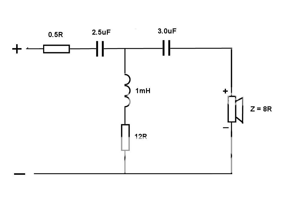
How do I figure out what the crossover point is for this part of the filter?
___________________________________
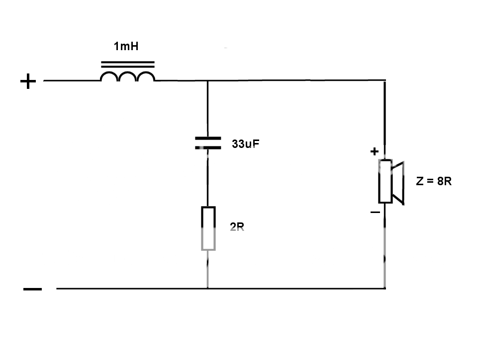
Here's the low-pass section of the crossover (2nd order filter):
Thanks in advance...
I've read some speaker design books, looked at a couple of crossover design spreadsheets, but I haven't found anything that would let me plug in values from a previously designed crossover and figure out what the theoretical crossover point will be. The calculators all seem to start from driver parameters and a desired crossover point, and calculate which component values you should use for this or that type of crossover.
My example is a Klipsch KG4.5 crossover. The high-pass section is a 3rd order, like this:
How do I figure out what the crossover point is for this part of the filter?
___________________________________
Here's the low-pass section of the crossover (2nd order filter):
Thanks in advance...
Last edited:
Speaker Workshop can do that I think, but you'd be assuming resistor-flat impedance for the drivers, without seeing what the drivers impedance and frequency response charts look like, there's no way to know for sure.
Thanks for your reply.
I'm not looking for precision, just a ballpark idea. For instance, it would be useful to me to know if the theoretical (electrical only) crossover point is in the neighborhood of 1000 Hz, instead of 2500 Hz. The 2nd order filter should be straightforward, what is it, 1/2pi(LC)? Or is that for 1st order only...
you'd be assuming resistor-flat impedance for the drivers, without seeing what the drivers impedance and frequency response charts look like, there's no way to know for sure.
I'm not looking for precision, just a ballpark idea. For instance, it would be useful to me to know if the theoretical (electrical only) crossover point is in the neighborhood of 1000 Hz, instead of 2500 Hz. The 2nd order filter should be straightforward, what is it, 1/2pi(LC)? Or is that for 1st order only...
I'm sure there was a time when certain people looked down upon others for using a slide rule. There's nothing wrong with using the equations manually, but I'd just download LTspice, plug in the circuit, and run an AC analysis. Then you'll have a powerful tool sitting on your hard drive that can answer a lots of other questions too.
(open in an image viewer actual size)
(open in an image viewer actual size)
Attachments

Last edited:
Thanks Andrew. DL'd LTspice, gave it a whirl, didn't get a good result the first time, but I'll keep at it.
--
--
+1I'm sure there was a time when certain people looked down upon others for using a slide rule. There's nothing wrong with using the equations manually, but I'd just download LTspice, plug in the circuit, and run an AC analysis. Then you'll have a powerful tool sitting on your hard drive that can answer a lots of other questions too.
(open in an image viewer actual size)
I do this , but using the drivers Le and Re and taking the output across Re.
Also using inductors Rdc can give very good 1st order approx of the electrical transfer function. Once you get good you can enter driver sensitivity as well. but remember acoustic response is important too esp if cross is near woofers linear or HF capabilities.
There are simple formulas for common crossovers that you can rearrange to get the frequencies. You have to assume a fixed resistance driver for those. For an arbitrary crossover or one that includes driver reactance you're talking circuit analysis. This requires complex values (j, the square root of -1) and you can do it by hand or you can do it by Spice, like LTSpice. IMO, it's not a bad idea to do it by hand once or twice, but you'll quickly start using LTSpice and never look back. If you want to learn how to do it by hand, get a text on basic-to-intermediate electronics like Boylstad's Introductory Circuit Analysis. I like the 5th edition, but it's up to the 11th and I see a lot of complaints. The later edition spends more time with Spice and the earlier edition does it by hand. No idea which is clearer, but definitely go with a cheap used copy. There may also be a download available. IMO, some version or another is an extremely good reference for the audio electronics DIY bookshelf. As Jim Williams would have said, "No home lab library is complete without a copy."
yes but doing "it" by hand can give different results for the breakpoints esp for BSC compensation. For Example in 'The Econowave' thread at AK they were talking about the 2 crossover frequencies? till I showed where it was really crossing over using LTspice.
Then somebody isn't doing "it" right! Are you saying that the response of complex circuits couldn't be calculated correctly until Spice was invented? I'd have some doubts about that 😀
not at all, but it would take "somebody" with adv engineering math and plotting it point by point, I don't think the OP had that in mind, unless he has help step by step. I'm just saying sometimes simple formulas are not the same thing as complex transfer function using vector math. IMO yer basically telling him to learn the equivalent of 2 or 3 college level courses, on the other hand he could learn LT spice on his own and get something useful reasonably quickly.
Last edited:
You'll notice I gave both options. No question if the goal is getting a fast and accurate answer, LTSpice is the way to go, though you still need a certain amount of understanding to be successful with that.
OTOH, I keep hoping there are people who still want to get to the root of things (no pun intended), and with the right books and questions it's within many people's capabilities, no advanced degrees required. It will take a certain amount of study and persistence, and yes you have to do it point by point. Excel however, wouldn't be cheating. It certainly doesn't take the equivalent of 2-3 college level courses if one had decent high school math.
OTOH, I keep hoping there are people who still want to get to the root of things (no pun intended), and with the right books and questions it's within many people's capabilities, no advanced degrees required. It will take a certain amount of study and persistence, and yes you have to do it point by point. Excel however, wouldn't be cheating. It certainly doesn't take the equivalent of 2-3 college level courses if one had decent high school math.
Last edited:
An interesting question that nobody wants to answer directly.
LC Filter Design
Try this web site. it is the opposite of your request in that it calculates the passive filter components given a frequency, order and load resistance. You can itterate backwards (adjust the request frequency until the L's and C's get reasonably close. You can also frequency scale: Since Z = jwL and 1/jwC a butterworth filter would have its components scaled by the ratio of its corner frequency to the values of a known frequency such as 1kHz.
For example: 1000 Hz and 8 ohms gives a high pass of 19.9uf, .64mH and 19.9uf. If your circuit has 9.95uf, .32mh and 9.95uf, then the values are halved so the corner frequency must be doubled. You would have a 2kHz filter.
As you are aware, virtually no good practical crossovers will be based on theoretical values. The one in your Klipsch example is odd with 12 ohms in the shunt leg. That would seriously overdamp it to the point where it is closer to first order than third. Networks to woofers usually need to compensate for high woofer inductance and extra midrange rolloff requirements. I've never compared practical to theoretical values but it would be interesting, and might lead to some generalizations.
David S.
You'll notice I gave both options. No question if the goal is getting a fast and accurate answer, LTSpice is the way to go, though you still need a certain amount of understanding to be successful with that.
OTOH, I keep hoping there are people who still want to get to the root of things (no pun intended), and with the right books and questions it's within many people's capabilities, no advanced degrees required. It will take a certain amount of study and persistence, and yes you have to do it point by point. Excel however, wouldn't be cheating. It certainly doesn't take the equivalent of 2-3 college level courses if one had decent high school math.
agreed, I'm still coming to grips with the understanding part my self. OTOH it probably would take me a greater part of the day coming up with the Xfer functions and the other half fiddling with Ecel, and after all that, the results would be questionable due not having the proper load ie driver info. Perhaps it's why I have some difficulty making that request for someone else to do.
The driver is the crux of it, making fools of us all  I don't have a good answer for that one without a lot of measurement that most people aren't equipped to do, and the truth of the matter is I quit building passive crossovers long ago. An active crossover is well behaved, uses small and easily obtained parts and the sum of the parts always seems to be a smoother and better defined system, even with modest power amps. On top of that it can be easier to experiment with crossover frequencies and levels.
Back to the OPs question, I assume he wants to do a bit of reverse engineering and better understand what Klipsch had in mind when they chose the frequencies they did. The electrical response is easy in LTSpice, but without knowing the acoustic output of the drivers the picture is incomplete. Now Andrew did the hipass part in LTSpice and the question was "How do I figure out what the crossover point is for this part of the filter?" It's important to note that the exact crossover point depends on what the lopass part of the design is doing. The crossover is obviously about 1500 Hz, but the really interesting thing to look at is the combination of hipass and lopass curves in that area. One can also assume the woofer is dropping off in that area, so the combined acoustic and electrical will drop faster. Lots to play with!
I don't have a good answer for that one without a lot of measurement that most people aren't equipped to do, and the truth of the matter is I quit building passive crossovers long ago. An active crossover is well behaved, uses small and easily obtained parts and the sum of the parts always seems to be a smoother and better defined system, even with modest power amps. On top of that it can be easier to experiment with crossover frequencies and levels.Back to the OPs question, I assume he wants to do a bit of reverse engineering and better understand what Klipsch had in mind when they chose the frequencies they did. The electrical response is easy in LTSpice, but without knowing the acoustic output of the drivers the picture is incomplete. Now Andrew did the hipass part in LTSpice and the question was "How do I figure out what the crossover point is for this part of the filter?" It's important to note that the exact crossover point depends on what the lopass part of the design is doing. The crossover is obviously about 1500 Hz, but the really interesting thing to look at is the combination of hipass and lopass curves in that area. One can also assume the woofer is dropping off in that area, so the combined acoustic and electrical will drop faster. Lots to play with!
Last edited:
FWIW I would question anybodys guess of crossover frequency at this point. I think just not enough info is there,..
LT spice baseline would be showing equal driver sensitivities, but I guess it depends on your definition of crossover point
Even if you had measured T/S parameters, there is obvious some acoustical data entering into all this due to assymetrical and highly damped filters.
LT spice baseline would be showing equal driver sensitivities, but I guess it depends on your definition of crossover point
Even if you had measured T/S parameters, there is obvious some acoustical data entering into all this due to assymetrical and highly damped filters.
Last edited:
The math is here if you want it: 2-Way Crossover Design / Calculator Help
Or you can take the easy way out and plug the values into something like PCD.
Given nominal 8 ohm impedances, you have a peaky 2nd order Butterworth LP at 1.1Khz and what looks like a very warped 3rd order HP at ~2.2K with a big rise of almost 10dB at the top. Maybe to counteract the falling response of a horn? I've done similar with horn loaded tweeters.
But as Dave points out, that's just the electrical response on the nominal impedances. The curves are likely rather different, and the acoustical curves certainly are. As you can see, figuring something like this can be tricky.
thanks everybody! Lots of good info for me.
I figured the calculated xover point would be just the electrical, not electrical+acoustical, but I wanted to get a very general idea of the approximate xover point. I figure it's in the 1000 to 1300 Hz range, which is fairly low for a 2-way -- and that's what I wanted to know (that info is missing from the Klipsch specs). I have a working hypothesis that I prefer 2-way speakers w/ xover point well below the usual 2kHz to 3khz point. I kind of like these speakers, so I wanted to see if that was a possible reason why. thanks, though, you all have been a big help.
I figured the calculated xover point would be just the electrical, not electrical+acoustical, but I wanted to get a very general idea of the approximate xover point. I figure it's in the 1000 to 1300 Hz range, which is fairly low for a 2-way -- and that's what I wanted to know (that info is missing from the Klipsch specs). I have a working hypothesis that I prefer 2-way speakers w/ xover point well below the usual 2kHz to 3khz point. I kind of like these speakers, so I wanted to see if that was a possible reason why. thanks, though, you all have been a big help.
I seriously doubt anyone would be crossing a smallish horn that low. my WAG would be ~ 1.8-2 KHz just from geometry and experience which means both break points would be further away.
BTW they list 6 ohms nominal impedance, seems more of a 2.5 way with a passive radiator. perhaps we are not seeing the correct schematic diagram.
BTW they list 6 ohms nominal impedance, seems more of a 2.5 way with a passive radiator. perhaps we are not seeing the correct schematic diagram.
Last edited:
I am not the electronics guy to ask and don't pretend to be. Just a thought , could you not attach the speaker to a generator feeding into an amp and then do some level measurements to see where the signal rolls? I would also be interested to see where the crossover point is. I know that the K79 tweeter has been measured by several folks and I have a response taken by Al Klappenberger which shows excellent response down to 2KHz. To ensure some protection for the tweeter you would have to roll it off above that. Best regards Moray James.
- Status
- Not open for further replies.
- Home
- Loudspeakers
- Multi-Way
- How 2 Calculate (theoretical) crossover point from a schematic