Hi everyone,
It's time for yet another 2-way standmount. This time i will use the following drivers:
Midwoofer:
ScanSpeak Revelator 15W/4531G00
Tweeter:
ScanSpeak Discovery D2608/913000 (also known as Peerless HDS 810921)
First I will do an active version based on the DEQX, then I will do a passive one.
It's time for yet another 2-way standmount. This time i will use the following drivers:
Midwoofer:
ScanSpeak Revelator 15W/4531G00
Tweeter:
ScanSpeak Discovery D2608/913000 (also known as Peerless HDS 810921)
First I will do an active version based on the DEQX, then I will do a passive one.
Attachments
First impression:
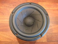
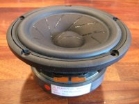
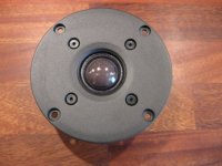
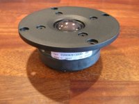
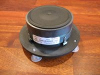
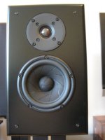
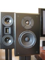
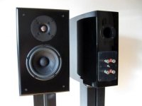
Both drivers have a nice build quality and finish. The woofer is built like a tank and the tweeter have an aluminum face plate and a double magnet. The woofers chassis are slightly darker in the finish, but they match each other quite well visually (Picture1 and Picture2) My reference loudspeaker is in the background.")
Even though the tweeter is from the entry level “Discovery” series, it has an impressive build quality and performance and I think it matches the more expensive Revelator midwoofer just fine.
Some facts from the manufacturer:
ScanSpeak Discovery D2608/913000 Tweeter:
• Very low mass soft dome diaphragm
• Ferrofluid
• Low resonance Frequency
• Optimized Magnet System with Double magnets
• Fully Vented Motor System for Low compression
• Black Die-Cast Aluminium Face Plate
ScanSpeak Revelator 15W/4531G00 Midwoofer:
• Patented Symmetrical Drive motor design
• Low-Loss linear suspension
• Die cast Alu Chassis vented below spider
• Sliced Cone (Controls Cone Breakups)
• Low Damping SBR Rubber Surround
• Large Ferrite Magnet System
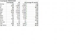
T-S Parameters:
The woofers where burnt-in with a signal generator for 24 hours before measuring the T-S parameters. It seems like that the T-S parameters are a bit off from the ScanSpeak spec sheets, but this seems to be the normal behaviour from many manufacturers and perhaps especially from ScanSpeak (Picture3).
The woofer seems to fit my Parts Express 14liter curved enclosures just fine, both when used as closed box and as a bass reflex box.
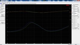
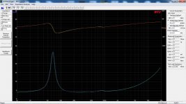
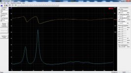
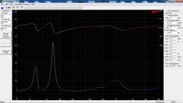
Impedance measurements:
The impedance measurements are made with the drivers mounted on the baffle and in the enclosure.
Picture 4: Tweeter #1 = Green, Tweeter #2 = Blue
Picture 5: Bass reflex box: Woofer #1 = Green, Woofer #2 = Blue
Picture 6: Closed box: Woofer #1 = Green, Woofer #2 = Blue
Note:
The impedance measurements show a perfect match between the woofers, but a close but not perfect match between the tweeters. The tweeter FS is around 800Hz which is about 100Hz higher than the spec sheet.
Comments:
The 14 liter box fit just perfect for use, both as a closed box version, as well as a bass reflex version. By subtracting the internal volume for the chassis and the bass reflex tunnel, we should have something like 13liters net volume. The bass reflex version is tuned to 39Hz and the closed box version has total Q of 0.69. The bass reflex version has an in room response down to the low 30:ies and the closed box to the mid 40:ies (I will measure it later on to confirm my first listening impression).
Right now I’m using the speakers in a DEQX configuration with two different correction filters. One uses a cross-over point at 2000Hz, 48db/octave, the other uses a 3000Hz, 48db/octave. Both correction filters uses a frequency measurement done at 15degrees off-axis at tweeter height and at a 2 meter distance.
Despite the fact that this is a quick and dirty configuration in order just to make them play and to burn-in the drivers, it sounds great. I have given them so far about 25-30 hours burn-in by playing music at a medium level. The first few hours the tweeters sounded a bit harsh, but they are beginning to loosen up considerably. The woofers midrange is very, very good and
The woofers frequency measurements are one of the best I have ever seen (more on that later on). The bass performance is also great and if I close my eyes and listen I could imagining a floor standing speaker in front of me.
I could stop here and just live with the speakers as they are now…. But that would spoil the fun of building a nice passive cross-over for them.
Next, frequency measurements………
Both drivers have a nice build quality and finish. The woofer is built like a tank and the tweeter have an aluminum face plate and a double magnet. The woofers chassis are slightly darker in the finish, but they match each other quite well visually (Picture1 and Picture2) My reference loudspeaker is in the background.
Even though the tweeter is from the entry level “Discovery” series, it has an impressive build quality and performance and I think it matches the more expensive Revelator midwoofer just fine.
Some facts from the manufacturer:
ScanSpeak Discovery D2608/913000 Tweeter:
• Very low mass soft dome diaphragm
• Ferrofluid
• Low resonance Frequency
• Optimized Magnet System with Double magnets
• Fully Vented Motor System for Low compression
• Black Die-Cast Aluminium Face Plate
ScanSpeak Revelator 15W/4531G00 Midwoofer:
• Patented Symmetrical Drive motor design
• Low-Loss linear suspension
• Die cast Alu Chassis vented below spider
• Sliced Cone (Controls Cone Breakups)
• Low Damping SBR Rubber Surround
• Large Ferrite Magnet System
T-S Parameters:
The woofers where burnt-in with a signal generator for 24 hours before measuring the T-S parameters. It seems like that the T-S parameters are a bit off from the ScanSpeak spec sheets, but this seems to be the normal behaviour from many manufacturers and perhaps especially from ScanSpeak (Picture3).
The woofer seems to fit my Parts Express 14liter curved enclosures just fine, both when used as closed box and as a bass reflex box.
Impedance measurements:
The impedance measurements are made with the drivers mounted on the baffle and in the enclosure.
Picture 4: Tweeter #1 = Green, Tweeter #2 = Blue
Picture 5: Bass reflex box: Woofer #1 = Green, Woofer #2 = Blue
Picture 6: Closed box: Woofer #1 = Green, Woofer #2 = Blue
Note:
The impedance measurements show a perfect match between the woofers, but a close but not perfect match between the tweeters. The tweeter FS is around 800Hz which is about 100Hz higher than the spec sheet.
Comments:
The 14 liter box fit just perfect for use, both as a closed box version, as well as a bass reflex version. By subtracting the internal volume for the chassis and the bass reflex tunnel, we should have something like 13liters net volume. The bass reflex version is tuned to 39Hz and the closed box version has total Q of 0.69. The bass reflex version has an in room response down to the low 30:ies and the closed box to the mid 40:ies (I will measure it later on to confirm my first listening impression).
Right now I’m using the speakers in a DEQX configuration with two different correction filters. One uses a cross-over point at 2000Hz, 48db/octave, the other uses a 3000Hz, 48db/octave. Both correction filters uses a frequency measurement done at 15degrees off-axis at tweeter height and at a 2 meter distance.
Despite the fact that this is a quick and dirty configuration in order just to make them play and to burn-in the drivers, it sounds great. I have given them so far about 25-30 hours burn-in by playing music at a medium level. The first few hours the tweeters sounded a bit harsh, but they are beginning to loosen up considerably. The woofers midrange is very, very good and
The woofers frequency measurements are one of the best I have ever seen (more on that later on). The bass performance is also great and if I close my eyes and listen I could imagining a floor standing speaker in front of me.
I could stop here and just live with the speakers as they are now….
But that would spoil the fun of building a nice passive cross-over for them.Next, frequency measurements………
Attachments

Hi gomir,
The 15w4531g00 is a drive a know well. I own it about 3 years in combo with a foutek JP3 tweeter. I good friend of my drawn me the filtre in serie topology. The 15w4531g00 is more than a nice unit. A really good one. I sell my couple but i keep the filtre mounted with secret desir to buy a new couple.
The proto box i've made
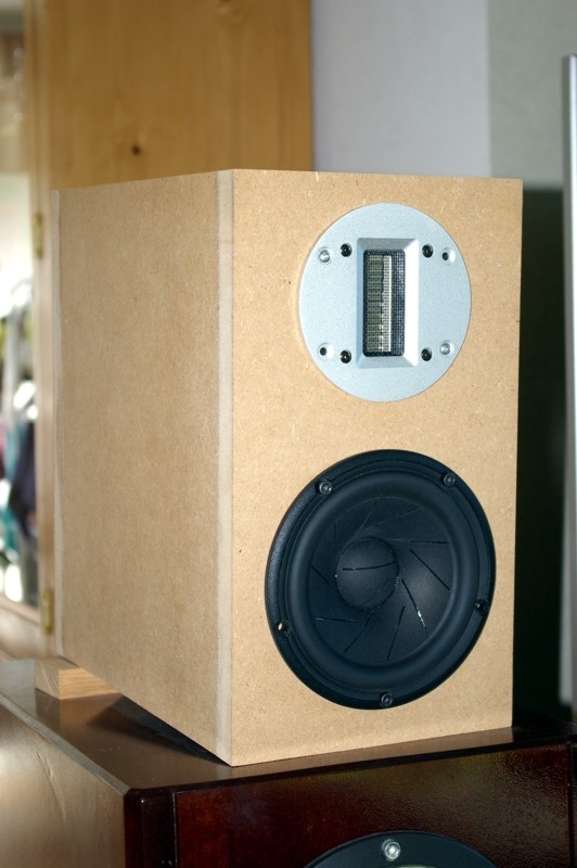
Filter
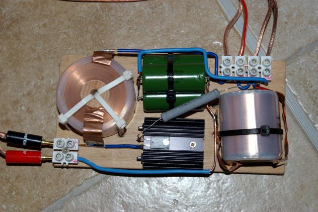
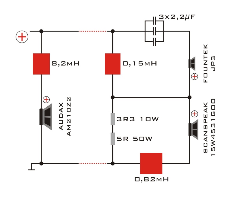
Ignore the left side the project was to couple them with 21cm woofer.
Why have you choosen 13L for box volume? It seem's to me to big. Mine was in 8.5L more you grown the volume more the drive is boomy...since the optimum was between 8.5L and 10L.
Marc
The 15w4531g00 is a drive a know well. I own it about 3 years in combo with a foutek JP3 tweeter. I good friend of my drawn me the filtre in serie topology. The 15w4531g00 is more than a nice unit. A really good one. I sell my couple but i keep the filtre mounted with secret desir to buy a new couple.
The proto box i've made
Filter
Ignore the left side the project was to couple them with 21cm woofer.
Why have you choosen 13L for box volume? It seem's to me to big. Mine was in 8.5L more you grown the volume more the drive is boomy...since the optimum was between 8.5L and 10L.
Marc
Hi Marc,
Thank you for sharing your design around the 15w/4531G00 woofer. It’s funny; I’m also having the Fountek JP3 ribbon as an alternative candidate to the design. Depending on how the woofer behaves in the upper frequencies and since I already own a pair of JP3, I might do a ribbon version later on.
You are right about that an enclosure of 8.5-10 liters would be suitable if the woofers did measure as the spec. sheets, but they don’t. They have lower motor strength (BL), higher FS and a lot higher Qts than the published parameters. I’m re-using my Parts Express 14liter cabinets from a previous project and it fits the sealed version perfect, but I have yet not decided on a final bass-reflex tuning. When the passive cross-over filter is in place I might reduce the volume slightly and tune it differently, but I personally tend to prefer some oversized box sizes and lower reflex tuning, which suites my listening room better.
To get an understanding of how I design my projects here is short sequence of how I work:
1. I tend to read a lot in magazines like “Klang & Ton”, “Hobby & Hifi” and in forums and blogs and in the manufacturer spec. sheets in the pursuit for new drivers.
2. Then I evaluate the frequency response and distortion plots to find a suitable interesting driver for a new project. Then I look if I have some tweeter or woofer in stock to pair it with (I tend to have a lot of tweeters in stock, somehow). For me it is important that the tweeter and woofer both fit technically but also aesthetically and visually in the design.
3. I buy the drivers and measure the T-S parameters and impedance. Then I calculate and simulate a box design to roughly get an idea on the volume size needs and enclosure shape.
4. I build, buy or re-use an enclosure from a previous design. I usually make the enclosure 10-20% bigger in volume. It’s easier to reduce an internal volume than increase and it gives me more flexibility with the box tuning and filter design later on.
5. I mount the drivers on the baffle and in the enclosure and do new impedance measurements on all drivers.
6. Nowadays I always do a quick and dirty active cross-over design in my DEQX system and let the drivers burn-in while playing music. This gives me a chance to test different cross-over points and get a general feeling of the drivers behaviour.
7. When the drivers are reasonably burnt-in I do the real frequency and distortion measurements. It tends to be a lot of measurements when I measure. At least I measure at 0, 15, 22.5, 30 and 45 degrees angle at tweeter height at 1m and 2m distance. I measure both left and right loudspeaker individually.
8. When I’m satisfied with the raw driver measurements in the actual enclosure I start to simulate a cross-over.
9. When I’m finished simulating the cross-over I start to build test prototypes and listen to them.
10. I measure the prototypes to see if it looks like the simulations.
11. I redo point 8-10 until I finally find a cross-over I like and which hopefully sounds great.
That’s just my approach of building a new project. Sometimes they take years, sometimes they never finish and sometimes they become great loudspeakers.
Regards
/Goran
Thank you for sharing your design around the 15w/4531G00 woofer. It’s funny; I’m also having the Fountek JP3 ribbon as an alternative candidate to the design. Depending on how the woofer behaves in the upper frequencies and since I already own a pair of JP3, I might do a ribbon version later on.
You are right about that an enclosure of 8.5-10 liters would be suitable if the woofers did measure as the spec. sheets, but they don’t. They have lower motor strength (BL), higher FS and a lot higher Qts than the published parameters. I’m re-using my Parts Express 14liter cabinets from a previous project and it fits the sealed version perfect, but I have yet not decided on a final bass-reflex tuning. When the passive cross-over filter is in place I might reduce the volume slightly and tune it differently, but I personally tend to prefer some oversized box sizes and lower reflex tuning, which suites my listening room better.
To get an understanding of how I design my projects here is short sequence of how I work:
1. I tend to read a lot in magazines like “Klang & Ton”, “Hobby & Hifi” and in forums and blogs and in the manufacturer spec. sheets in the pursuit for new drivers.
2. Then I evaluate the frequency response and distortion plots to find a suitable interesting driver for a new project. Then I look if I have some tweeter or woofer in stock to pair it with (I tend to have a lot of tweeters in stock, somehow).
For me it is important that the tweeter and woofer both fit technically but also aesthetically and visually in the design.3. I buy the drivers and measure the T-S parameters and impedance. Then I calculate and simulate a box design to roughly get an idea on the volume size needs and enclosure shape.
4. I build, buy or re-use an enclosure from a previous design. I usually make the enclosure 10-20% bigger in volume. It’s easier to reduce an internal volume than increase
and it gives me more flexibility with the box tuning and filter design later on.5. I mount the drivers on the baffle and in the enclosure and do new impedance measurements on all drivers.
6. Nowadays I always do a quick and dirty active cross-over design in my DEQX system and let the drivers burn-in while playing music. This gives me a chance to test different cross-over points and get a general feeling of the drivers behaviour.
7. When the drivers are reasonably burnt-in I do the real frequency and distortion measurements. It tends to be a lot of measurements when I measure. At least I measure at 0, 15, 22.5, 30 and 45 degrees angle at tweeter height at 1m and 2m distance. I measure both left and right loudspeaker individually.
8. When I’m satisfied with the raw driver measurements in the actual enclosure I start to simulate a cross-over.
9. When I’m finished simulating the cross-over I start to build test prototypes and listen to them.
10. I measure the prototypes to see if it looks like the simulations.
11. I redo point 8-10 until I finally find a cross-over I like and which hopefully sounds great.
That’s just my approach of building a new project. Sometimes they take years, sometimes they never finish and sometimes they become great loudspeakers.
Regards
/Goran
Hi goran,
Your approach in building speakers is a good one. Some 15w4531/SS9700 combo were built based on a french forum project then my version with JP3. The boomy face was many time observed when increasing volume. But that's all, only observed. I will follow this thread with attention.
Marc
Your approach in building speakers is a good one. Some 15w4531/SS9700 combo were built based on a french forum project then my version with JP3. The boomy face was many time observed when increasing volume. But that's all, only observed. I will follow this thread with attention.
Marc
Near field measurements:
A quick update! The last couple of days I have done hundreds of frequency measurements. I will not post them all, but I thought I should start to share some of the near field measurements.
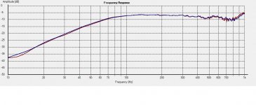
The woofer and port measurements are done at > 1cm distance. The tweeter measurements are done at 5cm distance.
Picture 1: Blue = Tweeter 1L, Red = Tweeter 2R.
Picture 2: Sealed enclosure. Blue = Woofer 1L, Red = 2R.
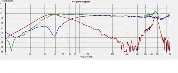
Picture 3: Bass-reflex enclosure. Blue = Woofer 1L, Red = Port, Green = Sum woofer+port.
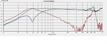
Picture 4: Bass-reflex enclosure. Blue = Woofer 2R, Red = Port, Green = Sum woofer+port.
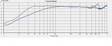
Picture5: Blue = Sealed enclosure and Green = Bass-reflex enclosure.
Comments:
Picture 1: A bit of disappointment here. The tweeter isn’t quite a perfect pair regarding the highest frequency response. In the cross-over region they are a close match. I will have to see if it will be noticeable when simulating the cross-over and if it can be heard. Thanks to the near field measurement there is no baffle diffraction present, but there is a broad dip in the response centered at 6,5kHz and there is a slightly rising top end.
Picture 2: When used in a sealed configuration there is an almost perfect match between both loudspeakers, -3db = 67Hz, -6db = 54Hz and -12db = 35Hz. Observe that this is a near field response and with no room gain added.
Picture 3 and Picture 4: Observe the notch in the woofers response where the port tuning is. The port response level is adjusted for the difference between the radiating area of the port and woofer. -6db = 32Hz and -12db = 25Hz. A strong port resonance is present at 650Hz. However the port is facing backwards and the resonance is not showing up in measurement made in front of the baffle.
Next frequency measurements……….
A quick update! The last couple of days I have done hundreds of frequency measurements.
I will not post them all, but I thought I should start to share some of the near field measurements.The woofer and port measurements are done at > 1cm distance. The tweeter measurements are done at 5cm distance.
Picture 1: Blue = Tweeter 1L, Red = Tweeter 2R.
Picture 2: Sealed enclosure. Blue = Woofer 1L, Red = 2R.
Picture 3: Bass-reflex enclosure. Blue = Woofer 1L, Red = Port, Green = Sum woofer+port.
Picture 4: Bass-reflex enclosure. Blue = Woofer 2R, Red = Port, Green = Sum woofer+port.
Picture5: Blue = Sealed enclosure and Green = Bass-reflex enclosure.
Comments:
Picture 1: A bit of disappointment here. The tweeter isn’t quite a perfect pair regarding the highest frequency response. In the cross-over region they are a close match. I will have to see if it will be noticeable when simulating the cross-over and if it can be heard. Thanks to the near field measurement there is no baffle diffraction present, but there is a broad dip in the response centered at 6,5kHz and there is a slightly rising top end.
Picture 2: When used in a sealed configuration there is an almost perfect match between both loudspeakers, -3db = 67Hz, -6db = 54Hz and -12db = 35Hz. Observe that this is a near field response and with no room gain added.
Picture 3 and Picture 4: Observe the notch in the woofers response where the port tuning is. The port response level is adjusted for the difference between the radiating area of the port and woofer. -6db = 32Hz and -12db = 25Hz. A strong port resonance is present at 650Hz. However the port is facing backwards and the resonance is not showing up in measurement made in front of the baffle.
Next frequency measurements……….
Attachments
Frequency measurements:
I have started the cross-over simulation and it looks promising so far, but first I will share some of the frequency measurements I have done on the drivers mounted in the actual enclosure I intend to use in the design (Parts Express 14liter curved enclosure, part # 302-721s).
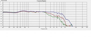
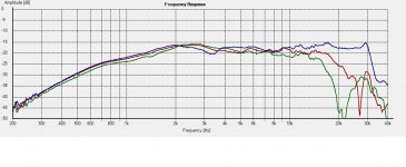
Even though I always measure both at 1m and 2m, all measurements shown here are made on tweeter-axis at 1m with no smoothing applied.
Woofer:
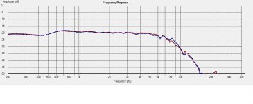
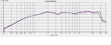
Picture1: Blue = Woofer #1, Red = Woofer #2.
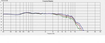
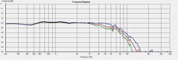
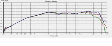
Picture2: Blue = Woofer #1 0 deg, Red = 15 deg, Green = 22.5 deg.
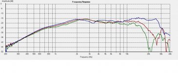
Picture3: Blue = Woofer #1 0 deg, Red = 30 deg, Green = 45deg.
Picture4: Blue = Woofer #2 0 deg, Red = 15 deg, Green = 22.5 deg.
Picture5: Blue = Woofer #2 0 deg, Red = 30 deg, Green = 45deg.
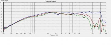
Tweeter:
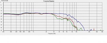
Picture6: Blue = Tweeter #1, Red = Tweeter #2.
Picture7: Tweeter #1 Blue = 0 deg, Red = 15 deg, Green = 22.5 deg.
Picture8: Tweeter #1 Blue = 0 deg, Red = 30 deg, Green = 45deg.
Picture9: Tweeter #2 Blue = 0 deg, Red = 15 deg, Green = 22.5 deg.
Picture10: Tweeter #2 Blue = 0 deg, Red = 30 deg, Green = 45deg.
Comments:
Picture1: This is one of the best midranges I’ve ever measured. Extremely linear and with an extended response up to 5000 Hz. Nice frequency match between Woofer #1 and #2.
Picture2-5: Very nice frequency response with a controlled roll-off and without any visible cone break-up. The woofer can be used up to 2700-2800Hz, without sacrificing any off-axis response behaviour.
Picture6: Unfortunately, there is not a perfect frequency response match between tweeter #1 and #2. Tweeter #1 has a rising top-end and tweeter #2 has an extended top-end. They both go very high up in frequency, 25kHz and 30kHz. Even though they don’t have an identical frequency response they are very close in the cross-over region. There shouldn’t be any problem with designing a cross-over for both tweeters.
Picture7-10: Baffle diffraction is clearly visible around 3500Hz, but evens out from >15 deg off-axis. There is a mild broad dip in response between 6.5-9kHz. Despite this tweeters size it has excellent off-axis response behaviour.
Next, cross-over simulation……..
I have started the cross-over simulation and it looks promising so far, but first I will share some of the frequency measurements I have done on the drivers mounted in the actual enclosure I intend to use in the design (Parts Express 14liter curved enclosure, part # 302-721s).
Even though I always measure both at 1m and 2m, all measurements shown here are made on tweeter-axis at 1m with no smoothing applied.
Woofer:
Picture1: Blue = Woofer #1, Red = Woofer #2.
Picture2: Blue = Woofer #1 0 deg, Red = 15 deg, Green = 22.5 deg.
Picture3: Blue = Woofer #1 0 deg, Red = 30 deg, Green = 45deg.
Picture4: Blue = Woofer #2 0 deg, Red = 15 deg, Green = 22.5 deg.
Picture5: Blue = Woofer #2 0 deg, Red = 30 deg, Green = 45deg.
Tweeter:
Picture6: Blue = Tweeter #1, Red = Tweeter #2.
Picture7: Tweeter #1 Blue = 0 deg, Red = 15 deg, Green = 22.5 deg.
Picture8: Tweeter #1 Blue = 0 deg, Red = 30 deg, Green = 45deg.
Picture9: Tweeter #2 Blue = 0 deg, Red = 15 deg, Green = 22.5 deg.
Picture10: Tweeter #2 Blue = 0 deg, Red = 30 deg, Green = 45deg.
Comments:
Picture1: This is one of the best midranges I’ve ever measured. Extremely linear and with an extended response up to 5000 Hz. Nice frequency match between Woofer #1 and #2.
Picture2-5: Very nice frequency response with a controlled roll-off and without any visible cone break-up. The woofer can be used up to 2700-2800Hz, without sacrificing any off-axis response behaviour.
Picture6: Unfortunately, there is not a perfect frequency response match between tweeter #1 and #2. Tweeter #1 has a rising top-end and tweeter #2 has an extended top-end. They both go very high up in frequency, 25kHz and 30kHz. Even though they don’t have an identical frequency response they are very close in the cross-over region. There shouldn’t be any problem with designing a cross-over for both tweeters.
Picture7-10: Baffle diffraction is clearly visible around 3500Hz, but evens out from >15 deg off-axis. There is a mild broad dip in response between 6.5-9kHz. Despite this tweeters size it has excellent off-axis response behaviour.
Next, cross-over simulation……..
Attachments
-
 Picture3.jpg140.1 KB · Views: 62
 -
 Picture2.jpg137.7 KB · Views: 78
 -
 Picture1.jpg134.3 KB · Views: 125
 -
 Picture4.jpg139.6 KB · Views: 70
 -
 Picture5.jpg141.1 KB · Views: 62
 -
 Picture6.jpg140 KB · Views: 79
 -
 Picture7.jpg144.5 KB · Views: 67
 -
 Picture8.jpg151.2 KB · Views: 72
 -
 Picture9.jpg151.3 KB · Views: 73
 -
 Picture10.jpg151.8 KB · Views: 54
Cross-over simulation:
Ok, its time for some cross-over simulations, but first I will share my thoughts about my design goals. Both drivers are well behaved and are quite easy to work with. This gives the opportunity to use different strategies regarding cross-over points and cross-over topologies etc. As a DIY designer you always have the possibility to choose these things according to you own personal taste and theories. I’m sure that you could find as many design solutions with these drivers as designers, but here is my design contribution:
Design goals:
I always set up some design goals when I’m starting my design construction. I might change some goals along the way of my work if I discover things that doesn’t work or things that I don’t like. Of course, my design goal always starts with choosing the drivers for the construction. I evaluate the drivers by reading spec sheets from the manufacturer, searching on internet for any independent frequency and distortion measurements and if they are used in other proven designs etc. All this gives me an overall general idea of how my design might look like. Then I buy the drivers and put them in a suitable enclosure and measure them as described in earlier posts.
Enough of that and back to business
This is my design criteria I set up for the SR551-HDS based on the above evaluation:
1. The drivers must fit in the Parts Express 14 litre curved enclosure, part # 302-721s.
2. Easily changeable between bass-reflex and closed box by using foam plugs.
3. Cross-over frequency somewhere between 2000-3000Hz.
4. Optimized cross-over based on the 15deg off-axis measurements.
5. Optimized off-axis frequency behaviour and dispersion.
6. Optimized drivers phase integration at 2.5meter listening distance.
7. Topology, LR 24db/oct acoustical cross-over slopes.
8. Nominal 4 Ohm loudspeaker with optional impedance correction circuit.
9. Adjustable tweeter level by swapping out one resistor.
10. Non complex cross-over with as few parts as possible.
11. High quality cross-over parts, especially parts in series with the drivers.
Design goal comments:
1. Nowadays I’m re-using different loudspeaker cabinets for my designs, since I simply haven’t the time to build new cabinets all time, even though I like building cabinets. I have a wide variety of cabinets, both factory made and home made. Consequently I focus on the most fun part of the design. The Parts Express 14 litre enclosure is slightly oversized for the bass-reflex version, but is almost perfect for the closed box version. When the cross-over is finished and placed inside the box, I might test to reduce the volume by 1-2 litres and see how it sounds.
2. Nothing much to say here, just an option.
3. Cross-over frequencies between 2000-3000Hz are within both drivers “comfort zone” regarding distortion etc. Both drivers are low distortion drivers and the tweeter could be used as low as 1500Hz distortion wise and the woofer could be used as high as 5000Hz based on the on-axis frequency measurements. However, there are other things to consider, like the off-axis dispersion and the frequency measurement suggests that the woofer can be used up to 2800Hz without sacrificing any off-axis dispersion (up to 45deg). I have used the woofer some time now in an active setup with my DEQX. I think the midrange this driver produce are on of the best I’ve heard. Therefore I will try to use it as high up in frequency as possible. Ok, why then use such a large (28mm) tweeter instead of a smaller ¾” tweeter you might ask? Yes that’s true, but the tweeter has a an extended frequency response and a very good off-axis dispersion and I really like sound of it. The sparkle and schimmer at the top-end is just great. With a high tweeter cross-over frequency, distortion won’t be any issue even when driven hard.
4. I will try to optimize the cross-over frequency and response for the 15 deg measurement, where the baffle diffraction effect isn’t that pronounced. This could mean that the on-axis response isn’t that pretty looking, but I think what happens off-axis with the frequency response and the drivers phase integration are more important. I see a lot of people trying to get a nice looking line as an on-axis response, but forget how the phase integration between drivers and the off-axis frequency looks like.
5. I’ve have mentioned it before, I will try to optimize the off-axis behaviour and I want a nice and even dispersion even at a 45deg angle.
6. I have measured the loudspeaker at both 1 and 2 meter distance and used it in my simulation. However I have primarily used the 1m measurements when doing my simulations, but have compensated the acoustical centre of the woofer in relation to the tweeter so it corresponds to a 2.5m measurement. There is no use optimizing a speaker entirely based on a 1m measurement and get the drivers phase integration optimized at 1m when you listen at a 2-4m distance.
7. These drivers are so well behaved so an option would perhaps be a LR 12db/oct cross-over slope. I gave it a thought, but decided to go with a LR 24db/oct cross-over, which is my favourite topology. I might later on see if a LR 12db/oct cross-over is doable.
8. This speaker will be considered as a 4 Ohm speaker with an option for a system impedance correction for those with a tube-amp.
9. The tweeter level should be adjustable according to personal taste by swapping out one single resistor without negatively affect the cross-over design.
10. My philosophy is “less is more” If I have the possibility to run a tweeter without e.g. any resistor in series with the tweeter, I do it because I think resistors degrades the sound. Unfortunately this is seldom achievable. I don’t believe in overdone cross-overs with 50+ components like another thread here in the forum http://www.diyaudio.com/forums/mult...-caps-cored-inductors-16-000-speakers-18.html . In my opinion this is a shortcut to kill the sound. I’ve actually heard this KEF loudspeaker at an audio show and now I know one of the reasons why I didn’t like them. If you need such an amount of components to build a speaker, why not go active e.g. DEQX or swap out the drivers to better ones or completely re-design? But that’s just my opinion
11. These are really nice drivers and think they deserve some premium cross-over parts, but I will not use any extreme priced cross-over components. In my opinion you should use quality components with good tolerances, but to use some of the highly priced cross-over parts out there is just ridiculous. My personal experience is that you should try to use fewer components instead. This gives a higher kickback rate than any overpriced components.
This is the end of my rambling this time. Next post will show the version 1.0 of the cross-over. Feel free to comment and tell me if I’m crazy or not, or if I’m on the right track? I can handle it. It’s just fun to discuss and share experiences and thoughts on the subject.
Next, cross-over simulation……
Ok, its time for some cross-over simulations, but first I will share my thoughts about my design goals. Both drivers are well behaved and are quite easy to work with. This gives the opportunity to use different strategies regarding cross-over points and cross-over topologies etc. As a DIY designer you always have the possibility to choose these things according to you own personal taste and theories. I’m sure that you could find as many design solutions with these drivers as designers, but here is my design contribution:
Design goals:
I always set up some design goals when I’m starting my design construction. I might change some goals along the way of my work if I discover things that doesn’t work or things that I don’t like. Of course, my design goal always starts with choosing the drivers for the construction. I evaluate the drivers by reading spec sheets from the manufacturer, searching on internet for any independent frequency and distortion measurements and if they are used in other proven designs etc. All this gives me an overall general idea of how my design might look like. Then I buy the drivers and put them in a suitable enclosure and measure them as described in earlier posts.
Enough of that and back to business
This is my design criteria I set up for the SR551-HDS based on the above evaluation:
1. The drivers must fit in the Parts Express 14 litre curved enclosure, part # 302-721s.
2. Easily changeable between bass-reflex and closed box by using foam plugs.
3. Cross-over frequency somewhere between 2000-3000Hz.
4. Optimized cross-over based on the 15deg off-axis measurements.
5. Optimized off-axis frequency behaviour and dispersion.
6. Optimized drivers phase integration at 2.5meter listening distance.
7. Topology, LR 24db/oct acoustical cross-over slopes.
8. Nominal 4 Ohm loudspeaker with optional impedance correction circuit.
9. Adjustable tweeter level by swapping out one resistor.
10. Non complex cross-over with as few parts as possible.
11. High quality cross-over parts, especially parts in series with the drivers.
Design goal comments:
1. Nowadays I’m re-using different loudspeaker cabinets for my designs, since I simply haven’t the time to build new cabinets all time, even though I like building cabinets. I have a wide variety of cabinets, both factory made and home made. Consequently I focus on the most fun part of the design. The Parts Express 14 litre enclosure is slightly oversized for the bass-reflex version, but is almost perfect for the closed box version. When the cross-over is finished and placed inside the box, I might test to reduce the volume by 1-2 litres and see how it sounds.
2. Nothing much to say here, just an option.
3. Cross-over frequencies between 2000-3000Hz are within both drivers “comfort zone” regarding distortion etc. Both drivers are low distortion drivers and the tweeter could be used as low as 1500Hz distortion wise and the woofer could be used as high as 5000Hz based on the on-axis frequency measurements. However, there are other things to consider, like the off-axis dispersion and the frequency measurement suggests that the woofer can be used up to 2800Hz without sacrificing any off-axis dispersion (up to 45deg). I have used the woofer some time now in an active setup with my DEQX. I think the midrange this driver produce are on of the best I’ve heard. Therefore I will try to use it as high up in frequency as possible. Ok, why then use such a large (28mm) tweeter instead of a smaller ¾” tweeter you might ask? Yes that’s true, but the tweeter has a an extended frequency response and a very good off-axis dispersion and I really like sound of it. The sparkle and schimmer at the top-end is just great. With a high tweeter cross-over frequency, distortion won’t be any issue even when driven hard.
4. I will try to optimize the cross-over frequency and response for the 15 deg measurement, where the baffle diffraction effect isn’t that pronounced. This could mean that the on-axis response isn’t that pretty looking, but I think what happens off-axis with the frequency response and the drivers phase integration are more important. I see a lot of people trying to get a nice looking line as an on-axis response, but forget how the phase integration between drivers and the off-axis frequency looks like.
5. I’ve have mentioned it before, I will try to optimize the off-axis behaviour and I want a nice and even dispersion even at a 45deg angle.
6. I have measured the loudspeaker at both 1 and 2 meter distance and used it in my simulation. However I have primarily used the 1m measurements when doing my simulations, but have compensated the acoustical centre of the woofer in relation to the tweeter so it corresponds to a 2.5m measurement. There is no use optimizing a speaker entirely based on a 1m measurement and get the drivers phase integration optimized at 1m when you listen at a 2-4m distance.
7. These drivers are so well behaved so an option would perhaps be a LR 12db/oct cross-over slope. I gave it a thought, but decided to go with a LR 24db/oct cross-over, which is my favourite topology. I might later on see if a LR 12db/oct cross-over is doable.
8. This speaker will be considered as a 4 Ohm speaker with an option for a system impedance correction for those with a tube-amp.
9. The tweeter level should be adjustable according to personal taste by swapping out one single resistor without negatively affect the cross-over design.
10. My philosophy is “less is more” If I have the possibility to run a tweeter without e.g. any resistor in series with the tweeter, I do it because I think resistors degrades the sound. Unfortunately this is seldom achievable. I don’t believe in overdone cross-overs with 50+ components like another thread here in the forum http://www.diyaudio.com/forums/mult...-caps-cored-inductors-16-000-speakers-18.html . In my opinion this is a shortcut to kill the sound. I’ve actually heard this KEF loudspeaker at an audio show and now I know one of the reasons why I didn’t like them. If you need such an amount of components to build a speaker, why not go active e.g. DEQX or swap out the drivers to better ones or completely re-design? But that’s just my opinion
11. These are really nice drivers and think they deserve some premium cross-over parts, but I will not use any extreme priced cross-over components. In my opinion you should use quality components with good tolerances, but to use some of the highly priced cross-over parts out there is just ridiculous. My personal experience is that you should try to use fewer components instead. This gives a higher kickback rate than any overpriced components.
This is the end of my rambling this time. Next post will show the version 1.0 of the cross-over. Feel free to comment and tell me if I’m crazy or not, or if I’m on the right track? I can handle it.
It’s just fun to discuss and share experiences and thoughts on the subject. Next, cross-over simulation……
Last edited:
Cross-over simulation:
Unfortunately it’s been a while since my last post because I’ve had some health problems and I’ve been working and sketching on a new 3-way high-end speaker http://www.diyaudio.com/forums/multi-way/197620-super-high-end-3-way-floor-stander.html
Anyway here is my cross-over simulation. It was quite easy to work with these drivers and to obtain my design goals (see my last post). I have built a version 1.0 of this cross-over and adjusted it slightly to a version 1.1. So far the adjustments I’ve done are in the tweeter damping section of the filter. There might be some additional adjustments (voicing) after I have done more listening tests. When I’m satisfied I will make control measurements to verify that the design measures as simulated.
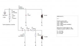
Picture 1: Cross-over filter v1.1
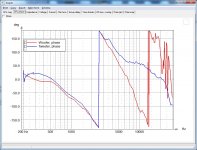
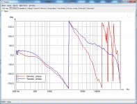
Picture 2: System impedance. Green=left speaker, blue=right speaker.
Picture 3: System impedance with impedance correction. Green=left speaker, blue=right speaker.
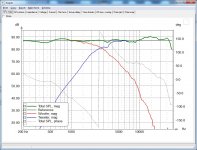
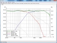
Picture 4: Tweeter-axis, 0 deg, 2.5m. 80db scale with no smoothing.
Picture 5: Tweeter-axis, 0 deg, 2.5m. Individual driver phase tracking response.
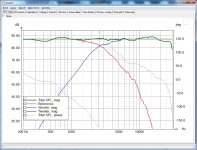
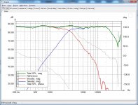
Picture 6: Tweeter-axis, 15 deg, 2.5m. 80db scale with no smoothing.
Picture 7: Tweeter-axis, 15 deg, 2.5m. Individual driver phase tracking response.
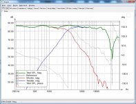
Picture 8: Tweeter-axis, 22.5 deg, 2.5m. 80db scale with no smoothing.
Picture 9: Tweeter-axis, 30 deg, 2.5m. 80db scale with no smoothing.
Picture 10: Tweeter-axis, 45 deg, 2.5m. 80db scale with no smoothing.
Comments:
My philosophy regarding cross-over designs is “less is more”. I don’t believe in throwing in tons of components and make unnecessary complex filters. Ideally I think as an example that if you can avoid using resistors in series for a tweeter, you are rewarded with a better sound. There is also no need in my opinion to “iron out” every little wrinkle in the response curve. If you still are in the need to do a lot of correction in the filter because of driver unit misbehaviours, I think you have chosen the wrong drivers for the design.
Thankfully in this design we have beautiful behaved drivers.
Picture 1. With such as well behaved and easy to work with drivers the cross-over schematics is very simple. The cross-over filter contains a second-order electrical filter section for the woofer and a third-order electrical filter section for the tweeter together with a simple L-pad damping in order to yield a LR fourth-order acoustical cross-over slopes at 2700Hz.
The system impedance correction is optional for those who want to flatten out the system impedance when using e.g. tube-amps.
Picture 2 & 3 shows the individual loudspeakers impedance, with and without the system impedance correction circuit.
Picture 4-10. I think I’ve found a nice balance in the cross-over. I managed to use the 15W mid-woofers full potential in the midrange by using it as high as 2700Hz and without losing any off-axis dispersion. The 15W midrange reproduction is quite simple, stunning and has a clarity in the upper frequencies where I think many mid-woofers fails to deliver.
The grey line shows the 87db 1m/2.83v reference level, which also is the loudspeakers sensitivity.
The woofers baffle step is very small when used on this baffle, only about 2db. With the chosen filter the loudspeaker has a full BSC.
By using a cross-over as high as 2700Hz, the tweeter reproduction is effortless. The HDS tweeter can be used as low as 1500Hz and in this design the tweeter has a safe margin in terms of distortion.
As can be seen in picture 4 & 6 (0-15deg), the tweeter is a bit “hot” in upper frequencies. This suggests little or no toe-in off the loudspeaker towards the listening position. I use no toe-in and it fits my room perfectly. I think the added energy in the top octave gives a more spacious and vivid sound and the HDS tweeter does it admirably without sounding aggressive, harsh or exaggerated in my opinion.
The level of the tweeter can be adjusted by changing the resistor R1 to somewhere between 1.5-3.9 Ohm and without changing the design adversely. I use 2.2 Ohm for R1 and it fits my taste and room perfectly, but it can be changed according to personal preference.
Next time I will post control measurements of the finished design.
Regards
/Goran
Unfortunately it’s been a while since my last post because I’ve had some health problems and I’ve been working and sketching on a new 3-way high-end speaker http://www.diyaudio.com/forums/multi-way/197620-super-high-end-3-way-floor-stander.html
Anyway here is my cross-over simulation. It was quite easy to work with these drivers and to obtain my design goals (see my last post). I have built a version 1.0 of this cross-over and adjusted it slightly to a version 1.1. So far the adjustments I’ve done are in the tweeter damping section of the filter. There might be some additional adjustments (voicing) after I have done more listening tests. When I’m satisfied I will make control measurements to verify that the design measures as simulated.
Picture 1: Cross-over filter v1.1
Picture 2: System impedance. Green=left speaker, blue=right speaker.
Picture 3: System impedance with impedance correction. Green=left speaker, blue=right speaker.
Picture 4: Tweeter-axis, 0 deg, 2.5m. 80db scale with no smoothing.
Picture 5: Tweeter-axis, 0 deg, 2.5m. Individual driver phase tracking response.
Picture 6: Tweeter-axis, 15 deg, 2.5m. 80db scale with no smoothing.
Picture 7: Tweeter-axis, 15 deg, 2.5m. Individual driver phase tracking response.
Picture 8: Tweeter-axis, 22.5 deg, 2.5m. 80db scale with no smoothing.
Picture 9: Tweeter-axis, 30 deg, 2.5m. 80db scale with no smoothing.
Picture 10: Tweeter-axis, 45 deg, 2.5m. 80db scale with no smoothing.
Comments:
My philosophy regarding cross-over designs is “less is more”. I don’t believe in throwing in tons of components and make unnecessary complex filters. Ideally I think as an example that if you can avoid using resistors in series for a tweeter, you are rewarded with a better sound. There is also no need in my opinion to “iron out” every little wrinkle in the response curve. If you still are in the need to do a lot of correction in the filter because of driver unit misbehaviours, I think you have chosen the wrong drivers for the design.
Thankfully in this design we have beautiful behaved drivers.
Picture 1. With such as well behaved and easy to work with drivers the cross-over schematics is very simple. The cross-over filter contains a second-order electrical filter section for the woofer and a third-order electrical filter section for the tweeter together with a simple L-pad damping in order to yield a LR fourth-order acoustical cross-over slopes at 2700Hz.
The system impedance correction is optional for those who want to flatten out the system impedance when using e.g. tube-amps.
Picture 2 & 3 shows the individual loudspeakers impedance, with and without the system impedance correction circuit.
Picture 4-10. I think I’ve found a nice balance in the cross-over. I managed to use the 15W mid-woofers full potential in the midrange by using it as high as 2700Hz and without losing any off-axis dispersion. The 15W midrange reproduction is quite simple, stunning and has a clarity in the upper frequencies where I think many mid-woofers fails to deliver.
The grey line shows the 87db 1m/2.83v reference level, which also is the loudspeakers sensitivity.
The woofers baffle step is very small when used on this baffle, only about 2db. With the chosen filter the loudspeaker has a full BSC.
By using a cross-over as high as 2700Hz, the tweeter reproduction is effortless. The HDS tweeter can be used as low as 1500Hz and in this design the tweeter has a safe margin in terms of distortion.
As can be seen in picture 4 & 6 (0-15deg), the tweeter is a bit “hot” in upper frequencies. This suggests little or no toe-in off the loudspeaker towards the listening position. I use no toe-in and it fits my room perfectly. I think the added energy in the top octave gives a more spacious and vivid sound and the HDS tweeter does it admirably without sounding aggressive, harsh or exaggerated in my opinion.
The level of the tweeter can be adjusted by changing the resistor R1 to somewhere between 1.5-3.9 Ohm and without changing the design adversely. I use 2.2 Ohm for R1 and it fits my taste and room perfectly, but it can be changed according to personal preference.
Next time I will post control measurements of the finished design.
Regards
/Goran
Attachments
-
 Picture3.jpg272.7 KB · Views: 89
 -
 Picture2.jpg272.3 KB · Views: 223
 -
 Picture1.jpg58.4 KB · Views: 238
 -
 Picture4.jpg196.5 KB · Views: 154
 -
 Picture5.jpg184.4 KB · Views: 134
 -
 Picture6.jpg196.5 KB · Views: 111
 -
 Picture7.jpg187.5 KB · Views: 92
 -
 Picture8.jpg200.9 KB · Views: 83
 -
 Picture9.jpg203.8 KB · Views: 100
 -
 Picture10.jpg207.5 KB · Views: 86
Last edited:
I have now finished the design and it’s renamed from the working name SR551-HDS to the “Revelation Two – Monitor”. Since my last post I’ve done additional tweeter damping tuning and finally made the last version of the cross-over after many hours of listening tests.
You can read about the design in detail on my new website:
www.audioexcite.com
www.audioexcite.com Revelation Two – Monitor
Summary:
The Revelation Two – Monitor is a medium sized stand-mount loudspeaker using two very high quality loudspeaker driver units from ScanSpeak. The design offers several tuning options in order to satisfy personal preferences and sound characteristics.
At a price of 1000-1200 US$ a pair it’s not exactly a cheap DIY design, but the sound and performance delivered from this loudspeaker usually costs several times more on the commercial market.
Sound description:
It is very hard to describe how a loudspeaker sounds like since it always will be a subjectively opinion, but here is my perception of the sound.
Despite the name “Monitor” the Revelation Two – Monitor isn’t a “Studio Monitor” used for near-field listening, but it brings out the details from recordings just like a “Studio Monitor” and it do so without ever sounding analytical cold, harsh or edgy.
The loudspeaker sounds bigger than its size indicates and it has a nice low end extension which reaches to the low 30:ies when room gain is added. The mid-range is wonderful natural and has an open character that doesn’t sound compressed or hard even on less good recordings. The tweeter is soft sounding with a nice vivid presentation and top-end sparkle.
When playing a well-made recording the loudspeaker really shines up and presents you with a very nice 3D perspective with a generous width, height and depth.
I have several designs on the workbench at the moment and I will soon start a new build thread.
Regards
/Göran
Attachments
Hi everyone,
I have updated the Revelation Two – Monitor design with distortion measurements of the finished loudspeaker.
The measurements confirm what you hear!
All distortion harmonics are low in the critical 1-3kHz frequency range. All odd-order distortion is low below 1kHz, while the harmless 2nd order distortion is a bit elevated between 300-1000Hz. The lower treble distortion is also kept low.
I have also updated the driver unit measurements section with distortion measurements for the ScanSpeak mid-woofer 15W/4531G00 and the tweeter D2608/913000.
For details see:
Distortion measurement -- Revelation Two – Monitor
Distortion measurement -- ScanSpeak 15W/4531G00
Distortion measurement -- ScanSpeak D2608/913000
Regards
/Göran
- Status
- This old topic is closed. If you want to reopen this topic, contact a moderator using the "Report Post" button.
- Home
- Loudspeakers
- Multi-Way
- SR551-HDS -- 2-way standmount