Measurement amplifier with ucd180.
http://www.hypex.nl/index.php?option=com_weblinks&view=weblink&id=10&catid=42
http://www.hypex.nl/index.php?option=com_weblinks&view=weblink&id=10&catid=42
Attachments
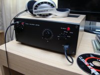
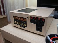
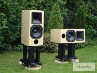
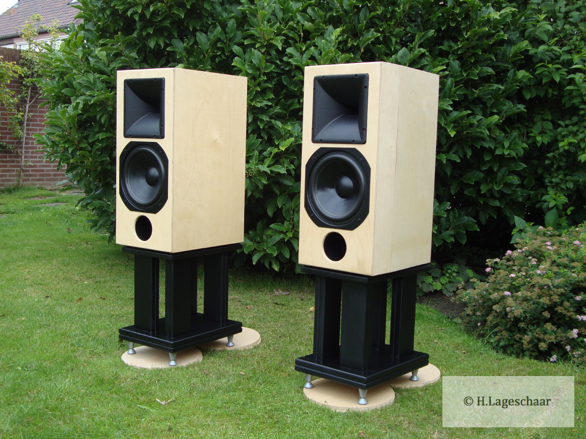
Design: As you can see I make all my equipment blackwhite with birch plywood.
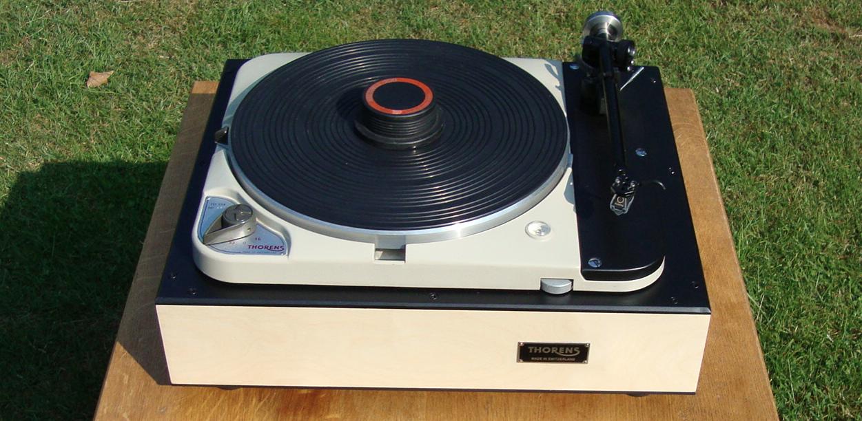
http://www.diyaudio.com/forums/analogue-source/189401-td124-mk1-rb301-new-plinth-service-6.html
http://www.diyaudio.com/forums/analogue-source/189401-td124-mk1-rb301-new-plinth-service-6.html
They look great. Is that an RCF H-100 horn?
Precise i did mount several 1" drivers like DE25 , CP350TI all work great on the low cost horn cut off 800Hz.
http://www.rcf.it/products/precision-transducers/horns/h100
1" HF-drivers
1" 35euro
http://bmsspeakers.com/index.php?id=bms_4524
1" down to 800hz
http://bmsspeakers.com/fileadmin/bms-data/product_data_2011/compression_drivers_ferrite/bms_4550_2011-04_hf_compression_driver.pdf
http://www.bcspeakers.com/CPD/product_pdf.php?id=0000000016
beyma brightsound titanium
http://profesional.beyma.com/ingles/pdf/CP350Ti.pdf
soft sound plastic
http://profesional.beyma.com/ingles/pdf/CP380M.pdf
http://www.rcf.it/en_US/products/precision-transducers/compression-drivers/n350
Last edited:
This speaker is the result for my search for compact high efficiency loudspeaker that can go down to 30Hz.
After many years of simulating my conclusion is physic laws dictate size and low cut off.
compact and high efficient means no subbas. When you want subbas you need to build big or loose some efficiency.
So this speaker is you have to see as high efficient with its 92dB at 1 Watt average sound pressure with this volume, was thought for tube amplifiers from 10-20W. So with 20W we have 115dB max SPL on 1 mtr and without compromising subbas and reasonable compact design.
And of course normal solid state will work to, up to 100W and I use my self the 180W class-D then you will hit x-max more when playing loud.
Last edited:
Let me explain a little for the guys here who have now exspirience with MLS.
A MLS measurement is used to measure the performance of a loudspeaker like in a anechoic room. The MLS technique enables you to trigger the test signal and discriminate room reflections.
Here I have a picture of a MLS Impulse that would be ideal when the speaker would measure like this. Note this one is inverted normal it would be positve.
Here the impulse of my speaker typical result for two way. It are two peaks one the first of the high response and one of the low-response. the second shows some smaller peaks that is not perfect it would be nice when it stopped after the second peak. Whit some experience one can tell it is a good pulse and measurement result.
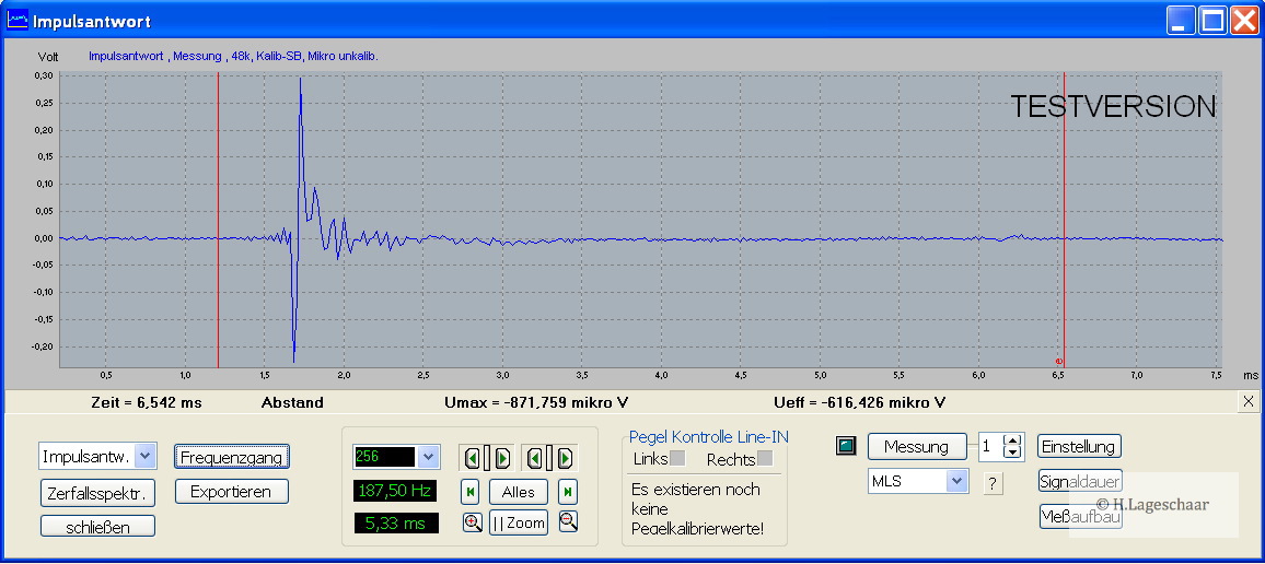
If a two way not shows the same like this and has a more messy long pulse it is a poor design.
A MLS measurement is used to measure the performance of a loudspeaker like in a anechoic room. The MLS technique enables you to trigger the test signal and discriminate room reflections.
Here I have a picture of a MLS Impulse that would be ideal when the speaker would measure like this. Note this one is inverted normal it would be positve.
An externally hosted image should be here but it was not working when we last tested it.
Here the impulse of my speaker typical result for two way. It are two peaks one the first of the high response and one of the low-response. the second shows some smaller peaks that is not perfect it would be nice when it stopped after the second peak. Whit some experience one can tell it is a good pulse and measurement result.
If a two way not shows the same like this and has a more messy long pulse it is a poor design.
In this figure is the speaker loudness red and I post with most measurements the minimum phase in ths figure bleu. A sudden chance in phase is the same as distorsion, in this figure you can see the minimum phase react on the lineair distorsion although it is very low here.
The perfect minimum phase would stay on the null line.
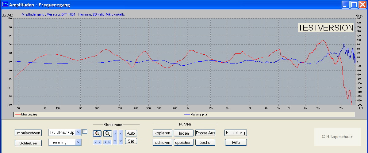
I do not see projects here where al this data is presented. It would nice reveal the faults in a design when its not pefect made.
Above 8kHz the horn driver got some ragged response. But here you cab see the minimum phase reacts on the spl changes.
The perfect minimum phase would stay on the null line.
I do not see projects here where al this data is presented. It would nice reveal the faults in a design when its not pefect made.
Above 8kHz the horn driver got some ragged response. But here you cab see the minimum phase reacts on the spl changes.
Last edited:
The speaker looks really nice!
It looks like you are using the horn turned 90 degrees. The curved sides are usually used to control horizontal dispersion and the straighter sides to control vertical dispersion. Why did you choose to do it differently?
You say you never see projects here that are documented like yours in this thread. I disagree. Many people post measurements of their loudspeakers, although not always the impulse response and phase. However, other measurements are more telling of faults or defects. These days many people post the frequency response on many different axes. I'd like to see such measurement of you speaker too! To see what I mean, please have a look at my most recent built: http://www.diyaudio.com/forums/multi-way/192737-2-way-waveguide-cardioid-like.html
My girlfriend did not like the speakers to be tall it was a idea to increase waf factor. And the horn is a 90/60 degrees type so when turned 90 degrees the dispersion changes. Then one have to decide whats the best for his application because the horn is sqaure.The speaker looks really nice!
It looks like you are using the horn turned 90 degrees. The curved sides are usually used to control horizontal dispersion and the straighter sides to control vertical dispersion. Why did you choose to do it differently?
The phase response looks like generated by boxsim, But i can't look good I have here a very slow vacation connection that is very difficult with loading pictures.You say you never see projects here that are documented like yours in this thread. I disagree. Many people post measurements of their loudspeakers, although not always the impulse response and phase. However, other measurements are more telling of faults or defects. These days many people post the frequency response on many different axes. I'd like to see such measurement of you speaker too! To see what I mean, please have a look at my most recent built: http://www.diyaudio.com/forums/multi-way/192737-2-way-waveguide-cardioid-like.html
(...)And the horn is a 90/60 degrees type so when turned 90 degrees the dispersion changes. Then one have to decide whats the best for his application because the horn is sqaure.
Why did you decide to use it this way?
The phase response looks like generated by boxsim, But i can't look good I have here a very slow vacation connection that is very difficult with loading pictures.
It's not generated by boxsim, it's the actual measured phase.
Why did you decide to use it this way?
I do not understand your question. The horn can be used the way you think it is best.
And I use the horn like Earl Geddes does, with controlled dispersion you can to some degree control your room reflection.
It looks that I am copying earl here that isn't the case I used in my first project 22 years ago also two horns, and struggled from designing on with the horn characteristics and how to understand it. Also with the question to have maximum dispersion or limited.
What also makes a horn desirable is the fact when it is big enough it gives a constant acoustic resistance seen as a perfect flat response. This good loading also leads to low distortion figures.
As end effect low distortion good linearity high efficiency controlled dispersion.
Also a poor dispersion is this a positive feature or negative. Can you tell that you have poor dispersion when you are in the sweat-spot?
If not I have to conclude the poor dispersion will help to discriminate room reflection thus room interference.
It's not generated by boxsim, it's the actual measured phase.
Then it would be better to measure with short gate for high frequency an long for low and paste the two together. And choose minimum phase because 180, -180 shows different with gating or sample rate it is confusing. Minimum phase is simple it has to stay "0" so it is easy to see what your speakers do with the phase.
In your third post the waterfall diagram shows quite a strong resonance at around 800hz, which is where you cross to the tweeter. i wonder, even while indeed the pro level tweeter is used far below it's rating, that the low xover frequency has something to do with that. Perhaps it is worth trying a xover at say 1200 hz.
Of course the resonance could be linked to your listening room instead of the speaker, but that seems quite a coincidence.
Of course the resonance could be linked to your listening room instead of the speaker, but that seems quite a coincidence.
Precise the measurements wher taken inside the house in the livingroom my listening room.In your third post the waterfall diagram shows quite a strong resonance at around 800hz, which is where you cross to the tweeter. i wonder, even while indeed the pro level tweeter is used far below it's rating, that the low xover frequency has something to do with that. Perhaps it is worth trying a xover at say 1200 hz.
Of course the resonance could be linked to your listening room instead of the speaker, but that seems quite a coincidence.
I think the waterfall measured outside will be cleaner.
Precise the measurements where taken inside the house in the livingroom my listening room. And I never mentioned a XO pointIn your third post the waterfall diagram shows quite a strong resonance at around 800hz, which is where you cross to the tweeter. i wonder, even while indeed the pro level tweeter is used far below it's rating, that the low xover frequency has something to do with that. Perhaps it is worth trying a xover at say 1200 hz.
Of course the resonance could be linked to your listening room instead of the speaker, but that seems quite a coincidence.
")
I think the waterfall measured outside will be cleaner.
Last edited:
Sound sample monitor-XL
I made a film to you let hear the loudspeaker the camera JVC HM330 does record bas very poor so only the mid high gives a impression on film.
Songs are from a 4cd boxure Brasil
YOUTUBE monitor XL - YouTube
I made a film to you let hear the loudspeaker the camera JVC HM330 does record bas very poor so only the mid high gives a impression on film.
Songs are from a 4cd box
ure BrasilYOUTUBE monitor XL - YouTube
Last edited:
- Status
- This old topic is closed. If you want to reopen this topic, contact a moderator using the "Report Post" button.
- Home
- Loudspeakers
- Multi-Way
- Project: monitor-XL reference values