Hi,
you must keep the same coil dimensions. That is all that will fit in the magnetic gap.
If the existing wire is round then square wire or rectangular wire may allow a little more copper in the gap.
That gives some flexibility in how you proportion the copper volume between length and cross sectional area.
More turns in the gap at the same cross-sectional area will increase sensitivity, if the weight of the coil remains the same.
A lighter dome and coil assembly should also give a change in sensitivity.
It is rather hard to answer your true question. Can you explain more what you are trying to do? WHY 2.5-4k? What is the application? What horn are you using?
A lighter compression driver may increase sensitivity, but at the expense of higher break-up distortion or possibly failure.
Changing the coil on an existing compression driver would be extremely difficult to say the least. And even if you can do it, there are always tradeoffs. If you used rectangular wire to squeeze more turns into the gap for the same resistance, the coil length becomes less and you have less excursion = lower output level. If you then lengthen the coil to regain the excursion, the resistance goes up so your voltage sensitivity goes down. The shape of the magnetic field modifies everything I just said.
--> sorry, there is no magic solution, only tradeoffs
...which is true of anything to do with speakers!
P.S. When you say your driver is 105 dB, how was that measured? On a plane wave tube? On a particular horn?
this disagrees with what I posted.If you used rectangular wire to squeeze more turns into the gap for the same resistance, the coil length becomes less and you have less excursion = lower output level. If you then lengthen the coil to regain the excursion, the resistance goes up so your voltage sensitivity goes down.
Have I got it wrong?
Can you explain more what you are trying to do? WHY 2.5-4k? What is the application? What horn are you using??
Its a siren .
-> sorry, there is no magic solution, only tradeoffs
...which is true of anything to do with speakers!
P.S. When you say your driver is 105 dB, how was that measured? On a plane wave tube? On a particular horn?
Its 105dB with 18 Inch horn flare. I was thinking that maybe if in my application as the frequencies below 2KHz and above 4KHz is never going come . Therefore I could go in with lighter diaphragm material , to sacrifice that frequency range .
Thanks
Buy a different driver. That's the easiest thing to do.
I was looking for 115dB sensitivity or more on CD 90/75 horn. But most of the mid range drivers are 105dB to 110dB at the most .
Higher sensitivity can be gained by using a tighter pattern horn, not by modifying the driver. Of course, this puts more sound on axis and less everywhere else. The highest I've ever seen are 114dB/m/W on a 20x40 for a 50mm exit with a 100mm coil.
If you really only need a narrow bandwidth, you could design a band pass filter (ie, crossover) with 3dB or so bandpass gain which will boost the output in exchange for a lower Zin.
If you really only need a narrow bandwidth, you could design a band pass filter (ie, crossover) with 3dB or so bandpass gain which will boost the output in exchange for a lower Zin.
...If you really only need a narrow bandwidth, you could design a band pass filter (ie, crossover) with 3dB or so bandpass gain which will boost the output in exchange for a lower Zin.
A rare but true suggestion. However, I'd really be wary what the impedance and phase angle ended up as, for fear of blowing the amp.
I should have said before that you could change to a lower impedance compression driver; that increases efficiency and sensitivity overall, still within limitations of coil length vs. magnet gap strength tradeoffs.
this disagrees with what I posted.
Have I got it wrong?
If I read you correctly, I'd say you have it not wrong but over-simplified.
Many companies like to advertise they are using rectangular or hex coil wire, to put more turns in the gap or just "more copper" in the gap, saying they use more of the magnet blah blah blah.
BUT.
More cross-section of copper means lower resistance. For the same coil length, this means the impedance becomes lower. For instance, if you just switch from round to hex wire with the same coil length, you'd have the same number of turns but lower resistance overall. [This might actually be good for the OPs unclear purposes, presuming his amp can handle it]
Let's presume though that you don't want the impedance lower-now you'll have to lengthen the coil, which means the same resistance but a heavier coil, which now decreases the sensitivity.
There are endless permutations, but my main point is you can't just talk about the cross-section of the wire in the gap. Coils are a tradeoff between length, resistance, outer diameter (which affects the magnet gap which affects the magnetic strength), and the number of turns of wire in the gap.
The amount of conductor in the gap doesn't matter, by the way, it is the number of turns times the strength of perpendicular component of the magnetic flux intercepting those turns. Flux outside the gap area can contribute significantly, at least in woofer designs.
Then you could use aluminum instead of copper...and on and on we go

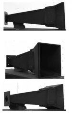
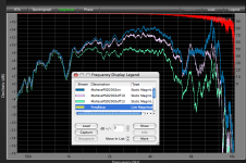
Using a standard Eminence PSD 2002 one inch exit driver, I measured about 115 dB one watt one meter mid band on my Maltese horn, using a 2” to 1” adapter.I was looking for 115dB sensitivity or more on CD 90/75 horn. But most of the mid range drivers are 105dB to 110dB at the most .
With a “real” driver the sensitivity is even higher.
However, as you can see, the Maltese horn is only about 15 x 15 degree dispersion above 3K.
Art Welter
Attachments
However, as you can see, the Maltese horn is only about 15 x 15 degree dispersion above 3K.
That thing looks like a "sonic disruptor". Make it hand-held and put a trigger on it....if only 2" drivers weren't so heavy
.I agree with all you have explained, but it appears you miss-read post2.If I read you correctly, I'd say you have it not wrong but over-simplified.
Many companies like to advertise they are using rectangular or hex coil wire, to put more turns in the gap or just "more copper" in the gap, saying they use more of the magnet blah blah blah.
BUT.
More cross-section of copper means lower resistance. For the same coil length, this means the impedance becomes lower. For instance, if you just switch from round to hex wire with the same coil length, you'd have the same number of turns but lower resistance overall. [This might actually be good for the OPs unclear purposes, presuming his amp can handle it]
Let's presume though that you don't want the impedance lower-now you'll have to lengthen the coil, which means the same resistance but a heavier coil, which now decreases the sensitivity.
There are endless permutations, but my main point is you can't just talk about the cross-section of the wire in the gap. Coils are a tradeoff between length, resistance, outer diameter (which affects the magnet gap which affects the magnetic strength), and the number of turns of wire in the gap............
Then you could use aluminum instead of copper...and on and on we go
some flexibility in how you proportion the copper volume between length and cross sectional area.
More turns in the gap at the same cross-sectional area will increase sensitivity
The amount of copper does matter. That is the only point I disagree with you on.The amount of conductor in the gap doesn't matter,
If you really only need a narrow bandwidth, you could design a band pass filter (ie, crossover) with 3dB or so bandpass gain which will boost the output in exchange for a lower Zin.
I can use DSP to design this BPF .... thanks for pointing this . Please elaborate a little on " lower Zin " ? do you say impedance would fall ?
Using a standard Eminence PSD 2002 one inch exit driver, I measured about 115 dB one watt one meter mid band on my Maltese horn, using a 2” to 1” adapter.
With a “real” driver the sensitivity is even higher.
However, as you can see, the Maltese horn is only about 15 x 15 degree dispersion above 3K.
Art Welter
Helpful example indeed , but this will reduce warning sound in nearby region due to its high DI . I googled but didn’t find much reference on ‘ Maltese horn’ a link/written material would be a great help.
Thanks
The amount of conductor in the gap doesn't matter, by the way, it is the number of turns times the strength of perpendicular component of the magnetic flux intercepting those turns. Flux outside the gap area can contribute significantly, at least in woofer designs.
This isn't true. Some analysis shows that force is proportional to B sqrd x L sqrd over Rdc, which is proportional to B sqrd x volume of conductor. Different dimensions and ratios of height to width of a ribbon conductor will change impedance but the volume of conductor in the gap is the primary factor impacting EM force.
Increasing the fill factor is key to increasing sensitivity. Clearance gaps and space wasted with insulation coatings knock the practical fill factor down to about 10%, poor indeed.
In general the efficiency will increase until coil mass equals diaphragm mass.
David S.
I can use DSP to design this BPF .... thanks for pointing this . Please elaborate a little on " lower Zin " ? do you say impedance would fall ?
DSP won't help - that bit of black magic only works with a passive filter *after* the amp. It can be designed to load the amp with 4 ohms with a 8 ohm driver, and gain 3dB. For that matter, a transformer would work - if you amp can handle a 2 ohm load use a 2:1 ratio and get every last milli-B you can out of it
. This sort of thing works *really* well to get earsplitting SPL out of a KSN1005 from a 9 volt battery. Now if I just had Welter's microwave feedhorn that would have been a lot of fun back in the day....If you really only need a narrow bandwidth, you could design a band pass filter (ie, crossover) with 3dB or so bandpass gain which will boost the output in exchange for a lower Zin.
That is a voltage sensitivity gain but not an efficiency gain. The impedance goes down as much as the voltage goes up.
Sounds like the OP wants a real efficiency increase (dB for a given wattage) It would be good to define the target efficiency. 1 acoustic watt is 109dB at 1m if radiating omni. The "per Watt" number will drop by true efficiency and the on axis SPL will increase by speaker directivity.
For example if your speaker is 10% efficient then you loose 10dB to get to 99 at 1 meter. If your Q (directivity) is 10, your d.i. is 10logQ, so it happens to be 10 and you are back to 109dB @ 1watt and 1 meter. This is for on axis only as part of the gain is through directivity rather than radiated power. 90 x 40 horns have a d.i. of about 10.5dB, 60 x 40 a d.i. of about 12.8dB.
Theoretically you can get 50% efficiency but I don't know if you can get over 20% in practice (Earl, are you out there?)
David S.
- Status
- This old topic is closed. If you want to reopen this topic, contact a moderator using the "Report Post" button.
- Home
- Loudspeakers
- Multi-Way
- Compression driver sensitivity