I think it's hard to appreciate just how many resonances there are in a speaker. Anything mechanical has a resonance, and resonances can't all be eliminated.If a cone has a resonance? All cones have many resonances. Even with todays design tools, the acoustical output of the many mechanical modes of any wooofer are still randomly addressed.
For some resonances the most you can hope for is to control them or push them outside the operating frequency range of the driver...
One might even say that as much as we don't want it to be the case, a completed speaker system (drivers, cabinets, crossovers etc) is a huge messy pile of carefully controlled, balanced and damped resonances
")
This is especially noticeable on a full range driver, as I was describing in my previous post. Whilst in a woofer a dust cap might not do much except contribute cone area, block air leakage paths, and keep foreign objects out of the gap, in any driver operating above >2Khz or so the dust cap is really important, and for a full range driver it's crucial.Dustcaps are one good variable for controlling top end frequency response.
Removing the dust cap on the Flat 8's kills the response above about 8Khz - it falls by many dB. A large portion if not the majority of the treble is radiating from the dust cap, so frivolously cutting it out completely changes the treble response.
I've wondered about the hole in the dust cap on the Flat 8's - it's about 8mm diameter in a 30mm dome, (with a tiny gauze behind it) and when they're producing bass you can really feel the air squirting in and out of the hole if you hold your hand close to it, but I can't say I've noticed a turbulence noise.It is the narrow passage that leads to turbulence and hence air noise.
I'm not sure whether the hole is there to minimize cone breakup that might otherwise occur in the middle of the dome in the treble, or whether its there to vent the pressure - the aluminum is extremely thin, dents rather easily, and I guess could be buckled or dented by the air pressure during bass if not vented.
Again relating to the Flat 8's - they don't have any venting or damping behind the dust cap, and this does appear to cause modulation of the treble with bass excursion due to the changing cavity size. The cavity is 30mm wide and 17mm deep, with an Xmax of +/- 3mm, so the cavity height can change from 14mm to 20mm with bass excursion peaks.A 3 to 1 variation in an under dustcap area? Thats a pretty good excursion.
The blips I've seen in impedance curves are more typically from the surround resonance, one of the lowest frequency resonances. I can't recall anything related to a back chamber Helmholtz resonance. If such a resonance exists I wouldn't worry about it varying with frequency but would just treat it. Many drivers have either venting through the pole or damping under the dustcap to deal with cavity resonances.
On the frequency response this shows up as a whole series of small but significant "ripples" which look like comb filtering which gradually start to appear from about 8Khz up which "slide" up and down in frequency with the cone position - you can see it clearly change with a real time FR analyzer when deflecting the cone with a DC bias. (It doesn't show up on the impedance curve though)
I assume that they only show up in the response at higher frequencies even though the fundamental cavity resonance is lower because only at the treble frequencies is the dome the majority contributor of the radiation of the driver. At lower treble / upper midrange frequencies although the resonance modulation of the cavity behind the dust cap is still occurring the dust cap is a rather small proportion of the total radiation area and is thus swamped by the response from the rest of the cone...
In hindsight I think this is a significant source of audible IM distortion between bass and treble - even if the motor and cone are fairly linear the bass excursion will amplitude modulate treble frequencies due to the "sliding comb filter". I'm pretty sure I can hear this at higher volume levels when using them full range, but when crossed over with a tweeter I can't hear any IM at the same playback levels.
A "phase plug" would eliminate the problem of course (at the expense of a large loss of treble) but I don't see why proper damping behind the dome wouldn't also solve the problem without killing the treble performance.
Last edited:
Didn't notice this at first, but something is very screwy with your CSD graph - 79ms on the time axis ?CSD is before and after.
Normally you would measure driver decay over 2 to 4ms or so. Apart from being impossible to do a reflection free 79ms gated measurement in a house, no driver should take that long to decay If you really did use a 79ms gate time you'll be collecting a ton of room reflections, so most of that decay will be room reverberation decay not the drivers own decay response, which should typically be at least ~25dB down in under 2ms.
Your CSD graphs also look very different to mine graphically even though I use ARTA as well. Old version of ARTA perhaps ?
Last edited:
If a cone has a resonance? All cones have many resonances. Even with todays design tools, the acoustical output of the many mechanical modes of any wooofer are still randomly addressed. Dustcaps are one good variable for controlling top end frequency response.
Of course the cone will have a resonance. However I was referring to a very problematic resonance that needs to be corrected for. As an example, a TD15M is +/- 2.5dB up to over 4KHz on axis while an AV15 has a very narrow breakup mode at 2KHz that is only about 1/4 octave wide but nearly 10dB in magnitude. Obviously the aluminum cone AV15 wouldn't be a driver suggested to play up to 1KHz. As another example, the initial cone samples I got for the TD6M with a standard hard pro-audio style paper pulp would play smoothly to 8KHz but then had a large breakup at 8.5KHz of nearly 10dB. I took a tip that Nick McKinney got from Roger Russell a long time ago and made a switch to a Kapok pulp for the cone. This is a softer pulp that is much more well damped internally. The driver now doesn't play as high, only to about 5KHz but then rolls off smoothly with almost no breakup. There is no dustcap that could correct this.
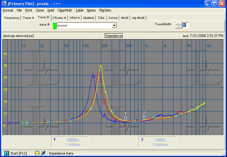
As another example, look at the 18sound 6ND410. This driver had many issues, but in this case it was the dustcap that gave it the claimed efficiency. They claim 101dB 1W which it only exceeds around the breakup peak at 4.5KHz. I tried everything to damp the resonance. Added mass, stuck foam on the cone, putty, nothing could fully correct the issues. The following is the impedance curve measured a few ways. Red was the natural impedance curve with no modifications. You can see the issues at 4KHz. I added mass to the dustcap to try to damp it. The resonance is still there but shifted lower in frequency as you can see in the blue curve. You can also see the Fs has shifted lower as the mass added was significant. Finally I just cut the dustcap off as you can see in the yellow curve. Fs raised very slightly but the bump from the dustcap resonance is gone.
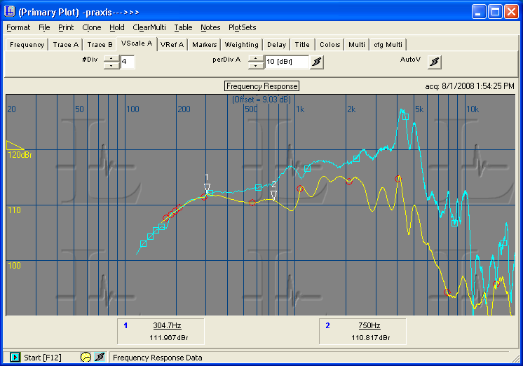
As I mentioned though, they count on this resonance for efficiency. You can see the effects of this dustcap on the entire bandwidth here. light blue is with the dustcap and yellow is without. Obviously this is an extreme example. It is literally the most extreme I have ever seen.
It is the narrow passage that leads to turbulence and hence air noise.
In order to have turbulence you need to have air flow. If there is sufficient resistance to prevent the airflow as I mentioned, there will be no turbulence or noise. Again, this simply comes down to proper design and taking these effects into account. Remember if you are dealing only with the box pressure inside the cabinet, this is easy to address. If you are however forcing air through the gap based upon the motion of the driver then the pressure can be substantially higher.
As a more common example, hook 100ft of 4" diameter hose up to a dust collector. You'll have noise at the far end as you are drawing a significant amount of air in. Now take 100ft of 1/4" hose and hook it up to the same dust collector. Same amount of pressure, same distance, but now you have much more resistance to the air flow. It will be completely silent as the flow is slowed to almost nothing even though the pressure is the same.
A 3 to 1 variation in an under dustcap area? Thats a pretty good excursion.
The larger the dustcap, the less this compression ratio will be obviously. However with many drivers using inverted dustcaps and highly extended poles now this chamber can be very small. As an example on the AV15's I have a 2.5" VC with a 1" pole vent. At 30mm inward excursion there is approximately 1/2" from the top of the pole to the bottom of dustcap. This gives about 2.5 cubic inches of volume under the dustcap. At 30mm forward this chamber is expanded to 14.8 cubic inches. In this case it is approximately a 5.9:1 ratio. Drivers that are even higher excursion like many of the XBL drivers out there now, the TC LMS drivers, etc will have an even higher ratio. The 3:1 I stated is quite conservative really.
The blips I've seen in impedance curves are more typically from the surround resonance, one of the lowest frequency resonances. I can't recall anything related to a back chamber Helmholtz resonance. If such a resonance exists I wouldn't worry about it varying with frequency but would just treat it. Many drivers have either venting through the pole or damping under the dustcap to deal with cavity resonances.
Everything that can resonate will. Spiders, cones, surround, dustcaps, air chamber under the spider, air chamber under the dustcap, etc. You can easily isolate which blip equates to which part. Just because there are other causes of resonance doesn't mean we just ignore some of them. It's also not only the issue of the resonance but also the difference in pressure within the chamber and the loading it places on the driver. You can put something inside the chamber, but that doesn't eliminate the issue, it only puts a bandaid over it.
Lots of myths flying here about "phase plugs". Some facts: these plugs do not act as phase plugs in the true sense: they do not improve response by equalizing path lengths or propagation times. They are generally not large enough to act as "reflectors" or even occluders of sound.
They may have a minor impact on frequency response. Simply leaving the dustcap off has the greater effect and removes a major variable that driver designers use to improve top end frequency response.
Agreed that the main benefit isn't in a woofer phase plug acting as a phase plug in the traditional sense. It's getting rid of the negative affects of the dustcap and air chamber under it that become the more important issue. There are some slight benefits in the upper response if a phase plug is long enough to come up to the front of the cone itself but they are very minor. I've never specifically seen a case where a dustcap improved the upper end response though. It has always been the opposite. If you want to damp a cone resonance, edge treatment at the outside of the cone where it attaches to the surround is a much more feasible option.
Removal of the dustcap always creates an air leakage path through the woofer. This may or may not create serious air noise at high excursion, depending on factors of coil and gap design, spider material, etc. You may get lucky or you may not.
I do agree that you likely won't have great results if you just take any random driver and remove the dustcap. If it hasn't been designed properly to prevent noise from air leakage then you will likely have problems. For something like open baffle use where there is no box pressure with a driver that has proper venting under the spider, the results could be good. If there is no pressure in the intended application there is no leakage. Also some initial testing can tell if the dustcap is the problem. Measure response and impedance. Add some mass to the dustcap. If the upper end response greatly changes and the bump in impedance curve shifts lower in frequency and is more broad, that is a good indication that the dustcap is an issue. If it doesn't change anything, go on to testing other things.
John
Last edited:
no advantage
There is no advantage to using a phase plug or open dust cap...none what so ever....with either you get a lot of out of phase signal eminateing from the driver.....Some people might think they are hearing more detail but they are hearing phase smear and group delay ? an out of phase signal ( time and phase) . . .this offsets any concern for cavity pressure or resonance...ask yourself this ? When have you ever scene a studio monitor, true studio monitor (stuff recording engineers use) or professional speaker with a phase plug or open dust cap...you don't and wont see them...if someone finds one to tell me about it is not one that is bought or used by anyone ! ! !...
You will also find many more monitors have rear facing ports than front; to keep out of phase midrange overwhelmed by direct signal. . . .vented voice coils, spiders and poles with damped dust caps do just fine regarding any resonance in the cavity...I have even scene wool felt on top of the pole to further damp dust cap radiation . . .
have a nice day,
~e~
Last edited:
Well, changing an existing well designed driver from a dust cap to a phase plug is certainly a crap shoot unless you have good measurement equipment and a lot of patience and time on your hands to develop exactly the right phase plug that will (hopefully) bring you back to a near flat response, but even then I agree you can easily end up worse off than you started, as in the example I gave.There is no advantage to using a phase plug or open dust cap...none what so ever....with either you get a lot of out of phase signal eminateing from the driver.....Some people might think they are hearing more detail but they are hearing phase smear and group delay ? an out of phase signal ( time and phase) . . .
Converting a full range driver from dust cap to phase plug seems to be a popular pastime amongst full range purists, (along with de-whizzering...) but whilst it certainly makes a significant change in the response I'm yet to be convinced that it's unambiguously a net positive result, or that it's even worth attempting.
The two main issues that it addresses (cavity resonance around 1-2Khz and dust cap resonance around 10Khz) can both be addressed in other ways IMHO, without the drawbacks of a "phase plug".
That's not to say that a well designed driver can't be made with a phase plug in the first place though.
I think that's being a bit harsh - I can think of at least one - the B&W Nautilus series (801 in particular) were sometimes used in recording studios - not as the near-field monitors obviously, but as full size monitors, and they have phase plugs in their midrange drivers. While they're not a speaker without flaws, I wouldn't point my finger at the phase plug as an issue in that design...When have you ever scene a studio monitor, true studio monitor (stuff recording engineers use) or professional speaker with a phase plug or open dust cap...you don't and wont see them...if someone finds one to tell me about it is not one that is bought or used by anyone ! ! !...
Agree 100% there. Ports on the front are a terrible terrible idea for midrange quality, especially on a 2 way but even on a 3 way, and something which I will never do again.You will also find many more monitors have rear facing ports than front; to keep out of phase midrange overwhelmed by direct signal. . . .
Doesn't matter how much stuffing is in the cabinet, (within reason) you'll get enough leakage in the midrange at the port's tube resonance frequency (often between 500-1000Hz) to cause easily measurable and audible colouration in the midrange. (More midrange output from the port at the resonance than from the driver is not uncommon even with a well lined cabinet)
It's not just out of phase either, the tube resonance causes a phase rotation that when summed with the drivers direct response results in both a peak and a notch in the FR, however as well as that the spurious output is also time delayed on the order of 2ms or more depending on cabinet/port size, smearing the signal badly in the time domain.
The exact same port on the rear of the cabinet eliminates the problem to the point where you can't measure it or hear it, even when the speaker is not far from the front wall, so there's no good reason I can see to put a port on the front baffle and a lot of reasons not to...
Last edited:
As another example, look at the 18sound 6ND410. This driver had many issues, but in this case it was the dustcap that gave it the claimed efficiency. They claim 101dB 1W which it only exceeds around the breakup peak at 4.5KHz. I tried everything to damp the resonance. Added mass, stuck foam on the cone, putty, nothing could fully correct the issues. The following is the impedance curve measured a few ways. Red was the natural impedance curve with no modifications. You can see the issues at 4KHz. I added mass to the dustcap to try to damp it. The resonance is still there but shifted lower in frequency as you can see in the blue curve. You can also see the Fs has shifted lower as the mass added was significant. Finally I just cut the dustcap off as you can see in the yellow curve. Fs raised very slightly but the bump from the dustcap resonance is gone.
It is not clear that the issue is a dustcap resonance. How do you know that is the case? Your two curves are dramatically different, almost looking like different woofers. One aspect not discussed yet is that dustcap removal loses woofer area and drops sensitivity. Your yellow curve looks like and extreme example of that, or is the difference due to the added mass?
As I mentioned though, they count on this resonance for efficiency. You can see the effects of this dustcap on the entire bandwidth here. light blue is with the dustcap and yellow is without. Obviously this is an extreme example. It is literally the most extreme I have ever seen.
This is not a typical with/without dustcap comparison. Again either the added mass is part of the difference or you have lost significant radiating area (I don't know what the dustcap diameter was). For most of the comparisons I've done the top octave peak and rolloff change with different dustcaps and the sensitivity drops a little from lost area. You can't really count on a resonance for efficiency as its bandwidth is too narrow.
As a more common example, hook 100ft of 4" diameter hose up to a dust collector. You'll have noise at the far end as you are drawing a significant amount of air in. Now take 100ft of 1/4" hose and hook it up to the same dust collector. Same amount of pressure, same distance, but now you have much more resistance to the air flow. It will be completely silent as the flow is slowed to almost nothing even though the pressure is the same.
Not sure that is a fair analogy. The volume of air pumped would be the same between a small gap and a large gap. Clearly, the velocity goes up with a smaller gap.
The larger the dustcap, the less this compression ratio will be obviously. However with many drivers using inverted dustcaps and highly extended poles now this chamber can be very small. As an example on the AV15's I have a 2.5" VC with a 1" pole vent. At 30mm inward excursion there is approximately 1/2" from the top of the pole to the bottom of dustcap. This gives about 2.5 cubic inches of volume under the dustcap. At 30mm forward this chamber is expanded to 14.8 cubic inches. In this case it is approximately a 5.9:1 ratio. Drivers that are even higher excursion like many of the XBL drivers out there now, the TC LMS drivers, etc will have an even higher ratio. The 3:1 I stated is quite conservative really.
John
We're talking about drivers with 60mm of excursion? Impressive woofers indeed. When people are talking about phase plugs I assume they are talking about modest output 6 or 8" units. If your woofers give you 60mm peak to peak then you should consider them as LF air pumps and assure that no midrange frequencies get to them. I can'timagine midrange sounding clean on top of 60 mm excursion for the usual IM (both FM and AM distortion) effects. I certainly wouldn't remove the dustcaps from such a woofer as there would highly likely be air noise problems at those excursions.
IM can be caused by several mechanisms at extreme excursions. Any mechanism that changes frequency response with excursion would create incidental IM for frequencies that varied in level. I have heard woofers with such high excursion that the coils were leaving the gap, the inductance was dropping dramatically (for the peaks of excursion) and HF energy was coming and going with the inductance variation. But I still haven't heard the effects of a varying under-dustcap Helmholtz resonance. (And if I did I would find a way to damp the resonance before considering removing the dustcap.)
David S.
Well, changing an existing well designed driver from a dust cap to a phase plug is certainly a crap shoot unless you have good measurement equipment and a lot of patience and time on your hands to develop exactly the right phase plug that will (hopefully) bring you back to a near flat response, but even then I agree you can easily end up worse off than you started, as in the example I gave.
Converting a full range driver from dust cap to phase plug seems to be a popular pastime amongst full range purists, (along with de-whizzering...) but whilst it certainly makes a significant change in the response I'm yet to be convinced that it's unambiguously a net positive result, or that it's even worth attempting.
Agreed.
It's not just out of phase either, the tube resonance causes a phase rotation that when summed with the drivers direct response results in both a peak and a notch in the FR, however as well as that the spurious output is also time delayed on the order of 2ms or more depending on cabinet/port size, smearing the signal badly in the time domain.
Just don't tell the TL people any of this.
David S.
Didn't notice this at first, but something is very screwy with your CSD graph - 79ms on the time axis ?
Thanks DBMandrake. I was attempting to extract off axis information from the on axis measurements, but I didn't mean to post them that way. Allow me to try again
First and second are before picking up the razor and after adding the plug. The third is without the dustcap.
Attachments
It is not clear that the issue is a dustcap resonance. How do you know that is the case? Your two curves are dramatically different, almost looking like different woofers. One aspect not discussed yet is that dustcap removal loses woofer area and drops sensitivity. Your yellow curve looks like and extreme example of that, or is the difference due to the added mass?
Please re-read what I posted. As explained, adding mass to the dustcap broadened and lowered the resonance. You can tell mass was added as the bottom impedance peak is lower in frequency in the blue curve. When I cut off the dustcap any mass added to the dustcap was also gone. The Fs is clearly higher than the original driver so there is now less mass. This was very specifically a dustcap issue. Not only did I add mass to it at one point, i damped it with the coating we use on cloth surrounds which shifted the breakup around. Cutting it off eliminated it completely. Again to be fair this was the most extreme case I have seen and not the norm. I also tested 6-7" drivers by B&C, PHL, Beyma, etc. Only the Beyma with the phase plug had a smooth upper end with little breakup.
This is not a typical with/without dustcap comparison. Again either the added mass is part of the difference or you have lost significant radiating area (I don't know what the dustcap diameter was). For most of the comparisons I've done the top octave peak and rolloff change with different dustcaps and the sensitivity drops a little from lost area. You can't really count on a resonance for efficiency as its bandwidth is too narrow.
See above. The diameter of the dustcap is 2.25" on a 7" driver. The VC however is 1.75" so that would be the amount of area lost. It can account for the loss of sensitivity somewhat but you can see that the entire shape of the response curve is now altered. The massive peak is gone and it is in general much more flat.
Not sure that is a fair analogy. The volume of air pumped would be the same between a small gap and a large gap. Clearly, the velocity goes up with a smaller gap.
IF the flow was allowed to fully pass through, and the passage could handle the pressure then yes this would be the case. However if the resistance is high enough, there is very little if any flow. You need enough pressure to overcome the resistance for any flow to take place. As another example take a garden hose. The water pressure connected to the hose is always a constant. You can calculate the flow rate based on the pressure and the hose length taking into account the resistance of the internal surface area of the hose. Now take a smaller hose again say 1/4" diameter the same length. While the length is the same and water pressure is the same, there is much more resistance to the flow. The velocity of the water coming out won't increase. It actually decreases due to added resistance and there is also much less flow coming out. The idea is to get the resistance up enough to eliminate any issues with velocity. If the internal pressure isn't significant enough to overcome the resistance through the small gap, it will never escape.
We're talking about drivers with 60mm of excursion? Impressive woofers indeed. When people are talking about phase plugs I assume they are talking about modest output 6 or 8" units. If your woofers give you 60mm peak to peak then you should consider them as LF air pumps and assure that no midrange frequencies get to them. I can'timagine midrange sounding clean on top of 60 mm excursion for the usual IM (both FM and AM distortion) effects. I certainly wouldn't remove the dustcaps from such a woofer as there would highly likely be air noise problems at those excursions.
I've been building and selling the TD woofers for about 6 years now. Previous to that Lambda Acoustics was selling them since 2001. Not all of them are that high excursion. That was actually an AV15 without phase plug to prove a point about the chamber volume. The TD15M's however are a 6mm Xmax driver with about 12mm one way suspension travel and clean response on axis to 4KHz. The phase plug instead of the dustcap is a huge part of that extended response as are the cloth surround and the cone profile and material. While the TD15M wasn't measured by augerpro, the LO15 was. This uses the same cone, surround, spider, but a shorter underhung coil. The physical soft parts are all the same so the breakups are primarily the same. Of most interest is the nearfield response, +/-2.5dB to over 3KHz:
(*edit - apparently you need to copy the link and past as it won't load here)

You can find the rest of the data here:
AE Speakers LO15 4ohm - drivervault
A TD15X or H though has 14mm Xmax and about 22mm one way suspension travel. Again the phase plug is instrumental in getting the clean upper end response. You can see the measurements augerpro did of the TD15X here:
Frequency Response - drivervault
There are no issues with air noise. Both the TD15M's and X's and H's are used for wide band use. I have TD15H's which are similar, but with a copper coil vs aluminum, in Studio 4 at Chicago Recording Company. The guy who claims that "nobody" uses drivers with phase plugs may want to check with them. I can give multiple other examples of those using them in studios but won't waste the time now.
IM can be caused by several mechanisms at extreme excursions. Any mechanism that changes frequency response with excursion would create incidental IM for frequencies that varied in level. I have heard woofers with such high excursion that the coils were leaving the gap, the inductance was dropping dramatically (for the peaks of excursion) and HF energy was coming and going with the inductance variation. But I still haven't heard the effects of a varying under-dustcap Helmholtz resonance. (And if I did I would find a way to damp the resonance before considering removing the dustcap.)
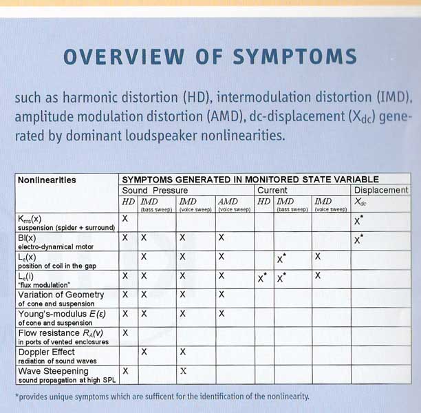
Yes there are many issues leading to IMD. The thing is that most often drivers are designed with intent to address one or two of the causes but in a way to ignore others. I often link people back to this poster as a good reference for the causes of various distortions.
As you mention, inductance variation is a huge issue for this. The typical S shaped inductance curve can cause some serious issues, especially when doing passive crossovers. If inductance is varying with excursion, so is the upper end of the response curve. As the impedance curve is also changing, values for passive crossover components are no longer valid to keep a good phase relationship at the crossover point either. Removing that variation is key to any wide band driver or any case when a driver has to be used in a region where the impedance curve has begun to rise, which is almost always. The full copper sleeve of the TD woofers linearizes inductance nearly perfectly. In fact all of the TD woofers measured by augerpro were excellent in Le vs X measurements. He stated when measuring the LO15:
"whippersnapper02@yahoo.com - Jun 26, 2009 9:30 AM
I know, why only the 5mm plot? Well this was the last TD driver I tested Le(x) for after seeing all the others what's the point? Put a well designed full copper sleeve on the polepiece and Le(x) will be excellent. In the case of ALL the TD drivers it's flawless.
"
As you an see in the TD15X at +/- 13mm there is no change in the impedance curve. (*edit - apparently you need to copy the link and past as it won't load here)

Not only that but the full copper sleeve also nearly eliminates flux modulation as well which is another HUGE factor in distortion, both IMD and harmonic, specifically odd orders. It's a reason that out of all the drivers tested the TD woofers also had the lowest distortion by a wide margin. Sorry if I got a little off track from the phase plug discussion here.
One final cause of IMD is due to varied acoustic loading on the cone. This leads to the properly sized phase plug argument. One of the things that were found to lead to IMD issues in the original TD drivers was the varied loading on the cone as the VC former came up around the curved portion of the phase plug. This was found by playing a 1KHz tone on top of a 20hz tone to high excursions. The solution in this case was a longer phase plug with a longer straight section before the curve. Once the former never came past the curved section, the loading was constant at all excursions and it eliminated this issue. In reality the shape of the plug at the point is nearly meaningless in the case of the woofer. It's the length that is the critical factor.
John
Last edited:
Not to be obtuse but I'm still not following your woofer comparison. They appear to be very different woofers measured under different circumstances.
There is an across the board 3 to 4 dB sensitivity drop. If the mass you previously added was removed (as shown in your impedance curves) and the area loss doesn't account for it then what is the difference? You can't claim that the dust cap resonances caused an across the board sensitivity difference, it just doesn't work that way. I also note that the measuring windows are different (fine fuzz on the cyan curve indicates a long measuring window). Plus a periodic wiggle around 1 k for the yellow curve indicates a strong reflection in the measurement not present in the other case. There are similarities in the dual peaks at 4.3 and 5 kHz, suggesting the same woofers but the other differences are too great for the changes you suggest.
A point on woofer peaks. Although most people assume that HF woofer peaks must come from the woofer center, most modal analysis shows that strong upper modes come from activity around the woofer cone's perimeter. Removing (or adding) a dustcap can be enough of a change to modify the output, but this does not indicate that the effect was purely happening on the dustcap (as evidenced by the 4.3 and 5k peaks still being there for both curves). At the same time your premise was that a strong resonance existed in the volume under the dustcap, the primary impetus for removing it. I'm still not seeing any evidence of that.
I'll stand by my initial assertions: removing a dustcap and adding a phase plug will take away a significant variable for adjusting the woofer frequency response, reduce the woofer's effective area and provide an air leak path that will frequently cause air noise problems. You can find the odd unit that overcomes all of these difficulties, but in most cases they are there. Certainly, pulling off a dustcap and adding a phase plug in hopes of improving a given woofer is misguided.
David S.
Attachments
![6nd410-modified-response[1].png](/community/data/attachments/223/223306-1842b7fb041606a9c7da807fd62872a4.jpg)
Not to be obtuse but I'm still not following your woofer comparison. They appear to be very different woofers measured under different circumstances.
There is an across the board 3 to 4 dB sensitivity drop. If the mass you previously added was removed (as shown in your impedance curves) and the area loss doesn't account for it then what is the difference? You can't claim that the dust cap resonances caused an across the board sensitivity difference, it just doesn't work that way. I also note that the measuring windows are different (fine fuzz on the cyan curve indicates a long measuring window). Plus a periodic wiggle around 1 k for the yellow curve indicates a strong reflection in the measurement not present in the other case. There are similarities in the dual peaks at 4.3 and 5 kHz, suggesting the same woofers but the other differences are too great for the changes you suggest.
I'm not sure what you aren't understanding here. This is the same woofer, measured on the same baffle with same windows. Measurements are taken one after another. Yes, the loss of area on a small 6.5" or 7" driver will cut some efficiency slightly. The breakup of the dustcap itself is not the only issue as I mentioned. The standard cone may have one major resonance. As you put a dustcap on you are attaching mass at another point. You now have 3 unique resonances. The area of the VC to dustcap, dustcap to outer edge, and dustcap itself. These all contribute. The additional efficiency difference may very well be from the loss of about 7% of the area.
It's clear that there is more of a wide band issue and not just at one point. The red curve shows a peak in the impedance curve that starts at about 3KHz and ends at about 5KHz. While it's typical to have small bumps, look at the magnitude of this one! Then look at the dark blue impedance curve. With a little mass added on the dustcap there is now an affect from 1500hz to over 4KHz. You can clearly see 3 distinct bumps indicating there very well may be 3 resonances that are all contributing.
A point on woofer peaks. Although most people assume that HF woofer peaks must come from the woofer center, most modal analysis shows that strong upper modes come from activity around the woofer cone's perimeter. Removing (or adding) a dustcap can be enough of a change to modify the output, but this does not indicate that the effect was purely happening on the dustcap (as evidenced by the 4.3 and 5k peaks still being there for both curves). At the same time your premise was that a strong resonance existed in the volume under the dustcap, the primary impetus for removing it. I'm still not seeing any evidence of that.
Correct that there are many causes and they don't all come from the center. The issues are often at the perimeter. Putting a dustcap towards the center has little to no effect on this. It will lower the distance from the perimeter to the first solid glue joint and often push the resonance higher in frequency as a result. Damping a resonance at the perimeter should be done at the perimeter. Various surround materials can make a difference. I always coat the back side of the paper cones where it attaches to the surround. This also makes a big difference.
In this case though, the 4.3K peak has dropped by 10dB and the 5K peak by nearly 15dB. The bump at 8K is gone and the 10k bump also decreased by 15dB. IMO this is a positive effect. The fact that adding mass to the dustcap itself shifted this resonance by an octave and broadened it so significantly indicates a dustcap issue. This wasn't the only testing done on this driver either. I added mass at many points around the cone itself. I added a felt ring around the ID of the surround. Neither had any affect on the large peak.
You can also often see these resonances with a stroboscope. This gives you a much better idea of where they are coming from and how to treat them. Linear X has a couple videos up demonstrating cone and spider issues on the page for their stroboscope:
LS310 - Precision Stroboscope - 1
I'll stand by my initial assertions: removing a dustcap and adding a phase plug will take away a significant variable for adjusting the woofer frequency response, reduce the woofer's effective area and provide an air leak path that will frequently cause air noise problems. You can find the odd unit that overcomes all of these difficulties, but in most cases they are there. Certainly, pulling off a dustcap and adding a phase plug in hopes of improving a given woofer is misguided.
IMO taking away another variable is a good thing. There is already an issue to deal with in terms of cone resonance. Why add a dustcap that has it's own physical resonance, adds another chamber of air that can resonate, and breaks up the cone area into two separate distances that both resonate. You are adding 3 resonance variables in an attempt to help take care of one. That seems very counter productive to me.
As I said before though I agree that pulling of a dustcap on any random woofer isn't typically a good idea. My experiments with the 18sound driver were specifically to find out why it sounded and measured so horrible. I did similar with multiple other drivers in attempts to learn some things before producing my own similar sized drivers.
The original topic was to discuss the reasons for a phase plug in a woofer. In the case of the woofers I build, it is very much a part of the heat transfer path. It also has a great amount to do with the clean high frequency extension of the drivers. My point was that it isn't the shape of the plug that is critical as in the case of a compression driver phase plug to control the high frequencies. It is the removal of the dustcap related issues in this case that significantly helps the upper end response. You can speak to the many thousands of people who have TD woofers that there are no audible issues with any kind of leakage around the phase plug.
John
All very interesting, and reasoned debate. However, whether audible or not, any appreciable air leak/pressure gradient between centre and edge of cone doesnt seem like a good thing, in ANY way at all, regardless what driver manufacturer. If i can hear the noise from a 3mm hole drilled into a sealed box speaker, and the marred performance it induces, id rather avoid a capless cone at all costs, and settle for a well designed vented pole. maybe a phase plug SHAPED cap would be ok...
All very interesting, and reasoned debate. However, whether audible or not, any appreciable air leak/pressure gradient between centre and edge of cone doesnt seem like a good thing, in ANY way at all, regardless what driver manufacturer. If i can hear the noise from a 3mm hole drilled into a sealed box speaker, and the marred performance it induces, id rather avoid a capless cone at all costs, and settle for a well designed vented pole. maybe a phase plug SHAPED cap would be ok...
If someone really wishes to calculate the effects, it is a basic fluids problem that takes into account the resistance created by the surface area the air passes over. It is the ratio of surface area to the cross sectional area that we are concerned with here. A 3mm hole through 3/4" mdf has about .28 square inches of surface area to create resistance to a cross sectional area of .011 square inches. This is not a hole that will have much resistance. An open screw hole in an enclosure can often be heard because of this lack of resistance. In a sealed box you could measure the Qtc of the enclosure, then drill a 3mm hole and measure again. You very well may see a shift in the Qtc and the measured Fc of the driver indicating that there is in fact an amount of leakage there.
The gap in the TD woofers has .063 square inches of open area, more than a 3mm hole. It also has over 100 square inches of surface area along a 7" long path to which the air must pass to "leak out". Based upon this surface area to cross sectional area alone, there is roughly 63 times more resistance to the air moving through the gap in the VC than in the 3mm hole. Then take into account a 180degree change of direction and the fact that the gap is so narrow nearly all the air is flowing within the boundary layer and there is realistically as much as 100 times the resistance as in the 3mm hole you mention. Take that same 3mm diameter hole and attach 75" of 3mm tubing to it. Then see if you can hear any leaking. You won't because the resistance is too high to allow for the flow.
I can build a TD15H with a dustcap and vented pole or with a phase plug and the "open gap." Using the delta compliance method measuring in a 50L sealed enclosure and in open air, both drivers show the same shift in Fc and measure with the same Qtc. Playing a 10hz test tone at full excursion to generate significantly high box pressure also shows no audible leakage. In the real world, it simply is not a factor.
The reputation for the TD woofers speaks for itself. I really don't need to. Ask those who have used them and those who have measured them in comparison to other drivers out there. The phase plug is a large part of what has lead to the reputation. The full copper sleeve on the pole is the other.
John
John,
I don't wish to debate this ad-nauseum so I'll take one last crack at it and then you can have the final word.
Your premise was that the volume under a dustcap would have a resonance, of itself not so bad, but due to woofer excursion being variable in frequency and therefor untreatable.
Your measurements don't back this up. The primary top end resonances you show in your measurements (4.3 and 5 kHz) are there both with and without the dustcap. They must be cone resonances. The only way I can think of to prove your assertion would be to measure frequency response with the woofer in different static positions, say when shifted with DC offset.
In the absence of that, I'd say the variable resonance argument is a straw man. As pointed out by others, any under dustcap resonance (if it was detectable) could be easily damped with an absorptive plug, or removed with a vented core pole.
There are further errors in your measurements. 1 (or 2 or 3) resonances can only raise level at their peaks and slightly in their skirts. Resonances will not cause a broadband efficiency change, yet your woofer curves show a 3 to 4 dB (and rising) response difference over multiple Octaves. Something else is going on. You mentioned felt rings, damping compound, and such. Were they still in place? The differences look more like considerable added mass, raised inductance (yes, unlikely) or a measurement from further off-axis. Other questionable differences between the curves are a different resolution ("fuzz" on the "dustcap" curve implies a longer measuring window, a regular periodic wiggle in the "no dustcap" case indicates a significant reflection in the measurement window). These are not comparable curves. They do not reflect the typical difference between a woofer with and without its dustcap, and they do not provide proof of any resonance under the dustcap.
I'm also not buying your assumptions about narrow air paths being silent. Adding flow resistance doesn't mean that air flow stops. For the most part a narrower path will increase velocity and make air noise worse. An absurd case would be to compare a small leak in a box (with attendant high air noise) to a vented box. Considerably more air can flow through the vent with no air noise at all. One of the most bizare cases of woofer noise that I've run across was a woven fiberglass cone with poor sealing. The minute holes in the cone mesh made a noise that sounded identical to crossover notch distortion and wouldn't go away until every last hole was sealed. High flow resistance did not stop the flow.
I'm not saying that you haven't cured all the potential problems of no dust cap with your woofer designs, just that the issues are there and the pitfalls, in my opinion, outway any possible benefits.
David S.
First, this is one of the most interesting threads I've found here in a long time. Very informative. It's good to see a discussion that stays genial even with disagreements.
The one comment I'd make is to not focus so much on bass drivers. Quite a few really good midwoofers use "phase plugs", such as those on the Seas metal cones. I know that the principles are the same, but the effects on the driver take on differences in importance.
To throw in my rather simplistic tests of a driver that has an extended dust cap, not a phase plug, it was surprising how small changes to cone and also directly to the dust cap improved the response. This dust cap is actually integral part of the cone (it's a cheap driver), but may add to the discussion.
As you mentioned John, the first thing to do may be to add damping to the surround if that resonance exists. A common treatment, but it does not seem to work well for soft cones that I've tested. That's the first thing I did to the driver tests shown here. It has not been a benefit on hard cones in my limited testing.
Blue - Untreated driver
Yellow - 3 coats of "The Wet Look" on the surround
Notice that practically all resonances were modified in one way or another.
The final configuration when I stopped testing did use damping on the dust cap. Much more than this quickly became detrimental.
Blue - Untreated driver
Yellow - 3 coats of "The Wet Look" on the surround and with damping "dots" shown

I did not make impedance measurement changes with the testing.
Given that Seas uses "phase plugs" in their hard coned series and a few select others, my impression is that the diaphragm material largely determines which method, plug or cap, has the best set of tradeoffs. There seems to be no single method that can be said to be "the best". This also ignores the case, seldom seen now, of resistive dust caps. I was always curious about those. I've got one older Seas 17W with this.
Dave
The one comment I'd make is to not focus so much on bass drivers. Quite a few really good midwoofers use "phase plugs", such as those on the Seas metal cones. I know that the principles are the same, but the effects on the driver take on differences in importance.
Let me offer that I might make a slightly different interpretation based on what I see. It does look like the increase in extension is due to the dust cap possibly due to excessive damping in the main cone limiting the extension coupled with the dust cap behaving as a small diameter radiator, somewhat the way whizzer cones work, only more controlled. But I also think I see what I initially interpret as the dust cap actually altering some excessive resonances in the main cone. These resonances appear to be highly destructive and broad, such as in the area 950, 1.2K, 2.9K, 3.8K, etc. Combined with the Q they tend to overlap and reduce the overall sensitivity, it actually looks like a lot of destructive interference, possibly due to how they exist within the geometry of the cone relative to phase issues. Add the small diameter radiator of the dust cap and it combines to give the extension/sensitivity. I'm basing this only on what I see, of course, so I'm speculating. Seeing some off-axis responses with the changes would help to separate the issues.As another example, look at the 18sound 6ND410. This driver had many issues, but in this case it was the dustcap that gave it the claimed efficiency. They claim 101dB 1W which it only exceeds around the breakup peak at 4.5KHz. I tried everything to damp the resonance. Added mass, stuck foam on the cone, putty, nothing could fully correct the issues. The following is the impedance curve measured a few ways. Red was the natural impedance curve with no modifications. You can see the issues at 4KHz. I added mass to the dustcap to try to damp it. The resonance is still there but shifted lower in frequency as you can see in the blue curve. You can also see the Fs has shifted lower as the mass added was significant. Finally I just cut the dustcap off as you can see in the yellow curve. Fs raised very slightly but the bump from the dustcap resonance is gone.
Again, I'm not sure that I follow this line. It appears that it may be more a case of eliminating some broad Q resonances in the driver that exist without the dust cap. Hard to say without seeing more SPL measurements of various tests.As I mentioned though, they count on this resonance for efficiency. You can see the effects of this dustcap on the entire bandwidth here. light blue is with the dustcap and yellow is without. Obviously this is an extreme example. It is literally the most extreme I have ever seen.
To throw in my rather simplistic tests of a driver that has an extended dust cap, not a phase plug, it was surprising how small changes to cone and also directly to the dust cap improved the response. This dust cap is actually integral part of the cone (it's a cheap driver), but may add to the discussion.
As you mentioned John, the first thing to do may be to add damping to the surround if that resonance exists. A common treatment, but it does not seem to work well for soft cones that I've tested. That's the first thing I did to the driver tests shown here. It has not been a benefit on hard cones in my limited testing.
Blue - Untreated driver
Yellow - 3 coats of "The Wet Look" on the surround
Notice that practically all resonances were modified in one way or another.
The final configuration when I stopped testing did use damping on the dust cap. Much more than this quickly became detrimental.
Blue - Untreated driver
Yellow - 3 coats of "The Wet Look" on the surround and with damping "dots" shown
I did not make impedance measurement changes with the testing.
Given that Seas uses "phase plugs" in their hard coned series and a few select others, my impression is that the diaphragm material largely determines which method, plug or cap, has the best set of tradeoffs. There seems to be no single method that can be said to be "the best". This also ignores the case, seldom seen now, of resistive dust caps. I was always curious about those. I've got one older Seas 17W with this.
Dave
Last edited:
Thats a good question and I can't fully answer it.
I go back 30 years in the industry and at my first job there were people stretching back another 30 (Essex Cletron) but the subject never came up. I've seen both the full mesh ones and the paper ones with a center vent hole covered by mesh or felt. Clearly they are used to give protection from metal particles falling into the gap while having no or minimal acoustical effect (the response altering effect of the typical dustcap, as we have been discussing). I remember them more on automotive products and MI (musical instrument) speakers.
I'm guessing the occasional driver designer got just the right response without a dustcap and didn't like the changes that available caps gave, so a screen cap would preserve the particular response. Alternatively, there might be the odd case where under-dustcap pressure was a greater problem than through-the-gap leakage.
I had never used them so I can only speculate on whats good about them.
David S.
So here is my dust cap popping story:
I was a junior engineer at JBL and had designed a small system called the L15. We got it into production and had the first run in the field when a Chicago dealer called up raving about how good the system was: "It is the only system in the store that reveals the hand clapping on Betty Davis Eyes ." (now you can date the story).
The sales rep thanked the store manager and ran over to engineering to ask what the difference was. I scrambled for a copy of the record and we put it on. Sure enough, when you turned the level up, the L15 was the only speaker that sounded like there was hand clapping in beat to the music. It turned out that the dust cap (formed paper) was inverting or "oil canning" with a snap sound when hit with a bass transient of the right frequency and level. We didn't find any other record that caused it but could duplicate it with an oscillator when we tried.
In the end a couple of stuck on foam pads on the back side of the dustcap cured it. I hear the tune every now and then on the oldies station and kind of miss the hand clapping.
Thats a good question and I can't fully answer it.
.
.
.
I had never used them so I can only speculate on whats good about them.
David S.
I have to correct my earlier post. The driver I had in mind is a Scan-Speak, the 18W/8543. It's a stiff, dense mesh, but does appear to be a weave, though it may not allow much air to pass through. I also dug out an old Fisher 8" with a big mesh that attaches midway up the diaphragm, it's not attached at the former, is very soft and definitely open. It may be something found mostly on cheaper drivers from the past. They don't have much mass, so it may have been a way to effectively protect as you say, but without reducing sensitivity or other acoustic parameters.
Now that's rich. I have to remember that one.So here is my dust cap popping story:
.
.
.
In the end a couple of stuck on foam pads on the back side of the dustcap cured it. I hear the tune every now and then on the oldies station and kind of miss the hand clapping.
Dave R.
I lack the engineering background to authoratively comment on the physics behind either the dustcap resonance issue or the air passage around the voice coil issue, but can offer some subjective comments based on experience with both types of woofers. My experience with woofers having phase plugs goes back to 2001 (when I bought my first set of Lambda Acoustics woofers from Nick McKinney), and my experience with woofers having dustcaps goes back to 1979.
Woofers with dustcaps seem to me more likely to have a nasty peak at their top end that makes the crossover more challenging. Maybe this is because my experience with woofers having phase plugs is limited to high quality examples (Lambda and Seas), while my experience with woofers that have dust caps covers a broader spectrum. So it would be premature of me to offer this up as a sweeping generalization.
One of the things I like to do when evaluating a woofer is to just listen to it fullrange all by itself, face-up on the living room floor. If it has good midrange clarity and articulation with no nasty peaks, that bodes extremely well for use in a two-way system. On this test, the big Lambda woofers are the best-sounding woofers I have heard regardless of size. No I haven't tested everything out there, but am extremely confident that a well-executed phase plug format woofer performs very well in the midrange.
Now regarding air passage around the voice coil, I haven't heard anything that sounds like either noise or a softening of bass impact on either the Lambda or Seas phase-plugged woofers. My experience with air leaks leads me to believe John's analysis on the subject, and let me explain why:
I build bass guitar cabs, and test them pretty thoroughly before they get shipped because they're going to be driven to their limits (and then some) by their owners. Occasionally testing reveals a small but audible air leak. Now it really doesn't take very much for an air leak to be audible; a little bitty all-but-invisible air gap around a port flange will do it. The fact that there are absolutely no audible signs of any air leaks on the Lambda woofers (whether manufactured by Nick McKinney or John Janowitz), tells me that, for all practical purposes, they do not leak. If there was enough of a leak to begin to have an effect on the bass, it would generate a clearly audible noise.
So, how does this affect the DIYer's purchasing decision? Well I'd say get the woofer whose performance is the best for your application within your budget, and if your budget could include woofers with phase plugs, for sure don't rule them out because of that feature.
Just for the record, I had a boutique woofer manufacturer develop a custom woofer for me, using a hemp cone and a multi-Faraday-ringed motor. I spent four thousand dollars having that woofer develped and a prototype built. Well, to my chagrin, the Lambda smoked it (hemp cone and all). Painfully bad pun intended. So anyway I kissed my four grand goodbye, and now use off-the-shelf Lambda woofers in my top-of-the-line models. In my opinion, there doesn't seem to be any downside performance-wise to using a good phase-plugged woofer.
Duke
- Home
- Loudspeakers
- Multi-Way
- Phase Plug?