 Nothing there to get in the way of the speaker (like there was in your first design idea)
SW S/R
At the time SW tutorial was written, Pentium III was the fastest cpu available and using high sample rates with high size was a tedious job. Now with modern processor and sound cards using higher S/R is a must; besides what is important when choosing the S/R in SW is to know at which S/R your cards works better. For example the SB Live works better at 48KHz than at 44KHz; for more info on how to know the best S/R to use for each card, take a look at my HP
Regards
Claudio
found the reference to 11Khz. doesn't really go into any great detail, but here it is.
At the time SW tutorial was written, Pentium III was the fastest cpu available and using high sample rates with high size was a tedious job. Now with modern processor and sound cards using higher S/R is a must; besides what is important when choosing the S/R in SW is to know at which S/R your cards works better. For example the SB Live works better at 48KHz than at 44KHz; for more info on how to know the best S/R to use for each card, take a look at my HP
Regards
Claudio
Thinking aloud:using higher S/R is a must
Using 11Khz S/R for example: the less quanitisation steps means the results look more consistent - but it's because the result is effectively smoothed out right?
But using higher S/R's means you get relatively varying results, but each probably more accurate than than those caluclated with a lesser S/R?
I think I need to do some tests...
Measured a midbass driver several times at two different sampling rates to see how much inconsistency there is.
No question that the lower sampling rate is more consistent, but the max difference for the higher rate is still pretty low I think.
joensd, I use 3D studio max.
No question that the lower sampling rate is more consistent, but the max difference for the higher rate is still pretty low I think.
joensd, I use 3D studio max.
Attachments
Vikash,
assuming you have re-calibrated SW for each S/R, assuming the REPEAT COUNT was set to more then one ( I use 10), assuming the burn-in time before starting the measuring was equal for both the S/R, I think the 48kHz has more datas; the differences are negligable. What would be useful is to know the Le value, since they differ (0,42 against 0,52) However I don't understand why not to use an impedance response 20/24000 instead of a 20/5500 if we can; isn't better to see the driver response in all the freq. range? And what happens when you measure the complete speaker impedance? You keep using the 11kHz S/R?
Regards
Claudio
Hi Vikash,
I remembered another thing that made a BIG difference for me. I was orginially using the speaker out on the Sound card (an original soundblaster), but found it much better when I fed the line out to my amp and drove the speaker under test with that.
Actually come to think of it, the second time I did measurements was after I bought a new sound card (turtle beach montego bay..... not available anymore because the chipset maker went belly up).... It has very good S/N ratio, and is supposed to be very good.
I'll be getting some new speakers soon, will have to try them with higher sampling rate, especially now I have a 2Ghz machine rather that the 400Mhz K6 I was using last time.
I still think though that sampling at a high rate probably gives some inconsistency due to the fact that the woofer is trying to produce all sorts of freq it's not designed to. I'm not sure whether SW limits the freq in the signal when the sampling rate is set lower (but if it does, I think that would explain it).
Regards,
Tony.
PS how does the curve look, is it like a porcupine or relatively smooth. Mine was looking like a porcupine, little spikes everywhere.
Hello
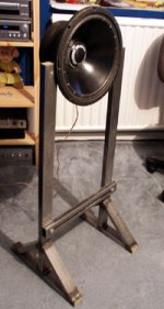
For those mad scientists like myself, who look for superfluous answers to simple problems, I give you illustrative results of my quest for a speaker measurement clamp.
Enjoy the madness
For those mad scientists like myself, who look for superfluous answers to simple problems, I give you illustrative results of my quest for a speaker measurement clamp.
Enjoy the madness
I was doing some impedance tests a while back and I discovered that one thing that affected the results greatly was whether or not the speaker was prevented from vibrating in mid-air. What I mean by this is, if for example the cone is 100 times lighter than the mass of the rest of the driver, then if the cone moves 10mm p/p then the rest of the speaker will move 0.1mm p/p in the opposite direction. Actually it will move a little more than that because the cone is pushing on the air.
Now, if you hold the speaker loosely by it's edge and look for an impedance peak you will get one for sure, but if you hold a brick against the centre of the rear of the magnet (don't block any vent holes!) so that any movement of the main mass of the speaker is reduced, then you will get a higher (and presumably more realistic) impedance peak.
I always stand a brick on end on a carpeted floor, and sit the magnet back on it, speaker facing up. Perhaps a 1 metre length of 100mm square redgum post would be a good way of doing it?
Speaker clamp
The old action / reaction thing Of course the driver vibrates more out of control as it reaches resonance, everything else seems to want to vibrate with it LOL!! I clamp the driver down tight to the workmate, works for me, it gives a smooth impedance plot without any anomilies with LMS.
Doug
The old action / reaction thing
Of course the driver vibrates more out of control as it reaches resonance, everything else seems to want to vibrate with it LOL!! I clamp the driver down tight to the workmate, works for me, it gives a smooth impedance plot without any anomilies with LMS.Doug
- Status
- This old topic is closed. If you want to reopen this topic, contact a moderator using the "Report Post" button.
- Home
- Loudspeakers
- Multi-Way
- Impedance measurement clamp - URGENT