I have a pair of Infinity Reference Standard II's and I want to build new crossovers since they are over 30 years old and I am sure the electrolytes have dried up long ago. The crossover points are 60, 125, 1500, and 3000 Hz and all seven drivers are 4 ohm. I am looking to build a second order Butterworth 5 way crossover, unless of course someone can talk me into some other route. Replacing the caps is not an option. (Anyone know where I can get a 1600uF 100VNP 85C metalized polypropylene cap? Me neither.)
Any chance you could use something like this or is this polarized? I don't know these things I just googled 1600 mfd caps.
MALLORY CGS162T400X4C3PH CGS 1600 MFD 400 VDC CAPACITOR | eBay
MALLORY CGS162T400X4C3PH CGS 1600 MFD 400 VDC CAPACITOR | eBay
Infinity Reference Standard II B and II A Loudspeakers
Let me say, that I am a little skeptical about the outcome of altering the crossover of these.
For instance, you could see that the two outer mids are crossed lower and the inner is crossed higher, thus forming a sound column, but also mimicking one single driver that has one single acoustic center. Every driver will narrow it's emitting surface (diameter) as the frequency rises.
In the link above, you will find the schematics for the bass equalizing unit if you do not have one.
A pair of these and a whole day listening session were one of the reasons for the ignition of my interest in this hobby. They were bi amped with a 500W Krell and a 500W Accuphase with Accuphase tube preamp... For the next year and a half or so, I was approaching the owner with various offers about the whole system, he never agreed to sell even though he is a professional audio equipment seller and those were in his showroom.") the components even had a price tags, but he said that he'll sell when he gets better system... five years later, he still haven't sold these
the components even had a price tags, but he said that he'll sell when he gets better system... five years later, he still haven't sold these
In addition, they are quazy acoustic suspension as the bass cabinet is ported with a port against the floor, so it is some sort of aperiodic enclosure.
From the crossover diagram Cal posted, it seems that the woofers have considerable coil inductance and considerable equivalent capacitance of the suspension and moving assembly. If you model a high mass, low QTS, low Fs, high Qms woofer with considerable Le in a software such as Bass Box, you'll find out that ordinary second order crossovers will induce or might induce a resonance peak at the crossover frequency and another resonance peak is possible several octaves above. I suppose that the top woofer circuit is designed to handle those issues - 5Mh+1,8Mh+125mf all shorted by Re and Le of the top woofer
Not to mention that both woofers in parallel with single crossover would produce allot more midbass than desired.
If I were you, I would restore the original crossover and obtain or build the bass eq unit if I didn't have one.
Also, those have a stated 25hz-25khz range and 29hz-25khz @+/- 2 db... Your 18 inch woofer might be loud, but does it do 25-29 hz @ -2 db?
Best Regards!
Let me say, that I am a little skeptical about the outcome of altering the crossover of these.
For instance, you could see that the two outer mids are crossed lower and the inner is crossed higher, thus forming a sound column, but also mimicking one single driver that has one single acoustic center. Every driver will narrow it's emitting surface (diameter) as the frequency rises.
In the link above, you will find the schematics for the bass equalizing unit if you do not have one.
A pair of these and a whole day listening session were one of the reasons for the ignition of my interest in this hobby. They were bi amped with a 500W Krell and a 500W Accuphase with Accuphase tube preamp... For the next year and a half or so, I was approaching the owner with various offers about the whole system, he never agreed to sell even though he is a professional audio equipment seller and those were in his showroom.
the components even had a price tags, but he said that he'll sell when he gets better system... five years later, he still haven't sold these In addition, they are quazy acoustic suspension as the bass cabinet is ported with a port against the floor, so it is some sort of aperiodic enclosure.
From the crossover diagram Cal posted, it seems that the woofers have considerable coil inductance and considerable equivalent capacitance of the suspension and moving assembly. If you model a high mass, low QTS, low Fs, high Qms woofer with considerable Le in a software such as Bass Box, you'll find out that ordinary second order crossovers will induce or might induce a resonance peak at the crossover frequency and another resonance peak is possible several octaves above. I suppose that the top woofer circuit is designed to handle those issues - 5Mh+1,8Mh+125mf all shorted by Re and Le of the top woofer
Not to mention that both woofers in parallel with single crossover would produce allot more midbass than desired.
If I were you, I would restore the original crossover and obtain or build the bass eq unit if I didn't have one.
Also, those have a stated 25hz-25khz range and 29hz-25khz @+/- 2 db... Your 18 inch woofer might be loud, but does it do 25-29 hz @ -2 db?
Best Regards!
Last edited:
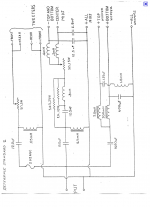
If what Cal posted is the diagram of the crossover of your speakers, what I said still applies.
And you can't make simple Butterworth crossover, because of the speakers impedance of 4 ohms. Inductances DCR plays crucial role in that crossover because if all were low DCR the amplifier would see terribly low impedance at some frequencies, particularly in the high frequencies.
And again, with that crossover are adressed both some pure acoustical issues and some driver specific issues.
For instance, have a look at the shape of the signal fed to the woofers, R1 is the woofer that goes to 125 hz and R2 is the one that is crossed at 60 hz.
I can bet on you that R1 is a kind of notch/impedance flattering device together with it's whole crossover for R2. Sorry I didn't sim the whole electrical equivalent of a driver, but the parameters of those are unknown for me.
R1 is fed with signal with a hole in it jut in the place where R2 would exhibit a peak.
Unfortunately, my competence extends only to the investigation part of it all.
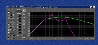
Now see the second attached picture, in it there are two plots, one of a bass system without a crossover - green and one with a crossover - lilac...
The first peak you get any time you use a second order Butterworth or similar crossover and the second is the bonus that you get with 4th order crossover of any type. That or similar or one that is a relative to those you could get with low crossover of a conventional design and a soft suspension woofer.
This is the principle of it, in practice the complex behavior would lead to different frequencies of the occurrence of those anomalies and some anomalies would not be evident due to the measures taken, but that does not mean that they do not exist
Best regards!
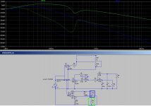
p.s. don't mind the values of the midrange and tweeter R's, I just altered them randomly to see what happens.
The lilac line in the second picture is fourth order @ 60 hz for an 8 ohm driver that I have and with parameters that are dully entered into the software... and... Zobel circuit does not help that situation... a transformer with a center point between primary and secondary grounded through a capacitor does help to some extent... but I haven't worked that out yet...
And you can't make simple Butterworth crossover, because of the speakers impedance of 4 ohms. Inductances DCR plays crucial role in that crossover because if all were low DCR the amplifier would see terribly low impedance at some frequencies, particularly in the high frequencies.
And again, with that crossover are adressed both some pure acoustical issues and some driver specific issues.
For instance, have a look at the shape of the signal fed to the woofers, R1 is the woofer that goes to 125 hz and R2 is the one that is crossed at 60 hz.
I can bet on you that R1 is a kind of notch/impedance flattering device together with it's whole crossover for R2. Sorry I didn't sim the whole electrical equivalent of a driver, but the parameters of those are unknown for me.
R1 is fed with signal with a hole in it jut in the place where R2 would exhibit a peak.
Unfortunately, my competence extends only to the investigation part of it all.
Now see the second attached picture, in it there are two plots, one of a bass system without a crossover - green and one with a crossover - lilac...
The first peak you get any time you use a second order Butterworth or similar crossover and the second is the bonus that you get with 4th order crossover of any type. That or similar or one that is a relative to those you could get with low crossover of a conventional design and a soft suspension woofer.
This is the principle of it, in practice the complex behavior would lead to different frequencies of the occurrence of those anomalies and some anomalies would not be evident due to the measures taken, but that does not mean that they do not exist
Best regards!
p.s. don't mind the values of the midrange and tweeter R's, I just altered them randomly to see what happens.
The lilac line in the second picture is fourth order @ 60 hz for an 8 ohm driver that I have and with parameters that are dully entered into the software... and... Zobel circuit does not help that situation... a transformer with a center point between primary and secondary grounded through a capacitor does help to some extent... but I haven't worked that out yet...
Attachments
Last edited:
Just re-read the thread. Beeferer, when you talked about dried caps, this is an opportunity to restore your crossover using quality parts. If you redesign it then unless you go to a large amount of effort, or have a small specific outcome in mind then you will in likelyhood make things worse.
It's not clear what speaker you actually have. A search shows up different speakers.
When I was first getting into audio, I remember lusting after one of the Infinity towers. None of them *look* like 5 way speakers that I've seen.
I'd be considering an active/passive hybrid at least with active bass, then replacing the caps making them up with multiple parts as needed. It would seem a shame to have to resort to electros to do it.
A little active conversion is a more ambitious project, but not insanely priced. MiniDSP is very cheap, measurement tools are also cheap. Perhaps more work than you had in mind, but worth considering.
Great speaker BTW. I'd just renew the parts with same values. The old Infinity did good work on their crossovers and this one is more difficult due to the OB mids and rear firing EMIT.
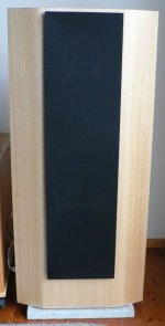
These would be them?
RS II
For caps, use MKP for the smaller sizes and these Mundorf bipolar are good for very high values.
Mundorf Bipolar Audio
These would be them?
RS II
For caps, use MKP for the smaller sizes and these Mundorf bipolar are good for very high values.
Mundorf Bipolar Audio

Where is that showroom?...he is a professional audio equipment seller and those were in his showroom.
- Status
- This old topic is closed. If you want to reopen this topic, contact a moderator using the "Report Post" button.
- Home
- Loudspeakers
- Multi-Way
- 5 Way Crossover design *HELP!*