Hello forum
Having read the main elements of this thread, I am readying myself to try this method on my first 2 way speaker build.
Before I go further here with the details...what is the number we use to determine tweeter attenuation level down -9db.? I have a hot tweeter and may well use BSC of -3db on the woofer.
The numbers stop at 6db.
Thanks
Go to Level Calculator
Strassacker: speaker - kits - tools
(it is comprised also in CRossover Calculator )
Strassacker: speaker - kits - tools
(it is comprised also in CRossover Calculator )
It sounds as though you are putting the resistor in parallel then wanting to add the L-pad. Can I suggest instead, just use 6 ohms in the L-pad calculator and don't worry about any of the other resistors. Ie: just the two that the calculator suggests.
Doing this will have the same effect of reducing impedance variation around tweeter resonance.
Doing this will have the same effect of reducing impedance variation around tweeter resonance.
The word Zobel is often used differently by speaker builders. In electronics it has a common meaning ie: compensating for impedance variations so that a load (eg the whole load) looks like a simple resistor.
Often with speakers it is used to describe an RC circuit, like the one used on the woofer in this thread. This is only a part of what Zobel is intended to mean, and I ask for clarification. An RC circuit does little for a tweeter the way they are normally crossed.
More important for a tweeter is the impedance variation at the lower frequencies around resonance. The ultimate conjugate (makes it flat) is a series RLC circuit (bandstop, notch) across the tweeter, providing a simple platform for future tweaking. However the combination of a parallel resistor and second order filter, especially when tweaked, can bring the correct response.
Last edited:
baffle step
Hi,
Could the following assumption make sense?
A 10" woofer with a sensitivity of 90dB
A 5,5” midwoofer with a sensitivity of 86dB
Mounted on a 12” (30 cm) baffle
Baffle step frequency : 115/.3 = ca. 380 Hz
If the woofer and midwoofer are crossed at ca. 400Hz, and the bafflestep Is taken into account, would the SPL of the midwoofer roughly match the woofer?
Thinking 'outside the box' this way saves you from attenuating the mid.
Each of the two drivers is affected by the baffle, each in more or less the same way. When you filter each you would be best to consider the effect this is already having, to subtract this from the filter you are adding.
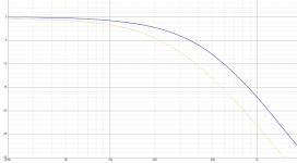
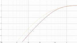
To make this easier to visualise I ran a sim.
[I used 6dB difference to keep things ideal, you chose 4dB which is more practical. The difference is not clear cut which is why I avoided using 4dB for the sim.]
What this shows is what each driver response should look like (darker trace), vs the amount of filter effect required to achieve it considering the baffle effect. Eg: The first (woofer) plot shows that you need to cut more to compensate for the rising response. This can mean using a larger inductor, aiming for a lower cutoff frequency than first expected.
Each of the two drivers is affected by the baffle, each in more or less the same way. When you filter each you would be best to consider the effect this is already having, to subtract this from the filter you are adding.
To make this easier to visualise I ran a sim.
[I used 6dB difference to keep things ideal, you chose 4dB which is more practical. The difference is not clear cut which is why I avoided using 4dB for the sim.]
What this shows is what each driver response should look like (darker trace), vs the amount of filter effect required to achieve it considering the baffle effect. Eg: The first (woofer) plot shows that you need to cut more to compensate for the rising response. This can mean using a larger inductor, aiming for a lower cutoff frequency than first expected.
Attachments
Last edited:
Designing a crossover for a quality 2-way PA speaker
Greetings,
I am making two PA speakers for a medium club live music band (my band!). They are to be 2-way speakers, with low end handled by one RCF MB12N301 – 8 Ohm, a 12¨ bass/mid-bass woofer, with Neodymium magnet. Detailed specs are attached.
High end is to be handled by a PA ribbon speaker... specs attached. Ribbon speaker is to be attached to a cast metal horn (70x30 degrees -- horizontal x vertical distribution).
I need someone who would design a complete(ly) passive crossover for this speaker (make schematics and layout) – with top notch components (no need to save money here, it would be stupid) – and perhaps also build two such crossover devices, to be installed in two speaker enclosures that I am making (each a vented enclosure with almost 40 liters of internal volume, tuned to 65 Hz, with one rectangular port).
Crossover frequency is to be 1,4 kHz. Minimum crossover slope should be 12dB/octave. It would be better if it would be 18dB/octave if no major losses are incured (12 or 18 dB per octave - debatable?).
Peak power that both those drivers can handle, short term (perhaps 100 msec?) is 1000 Watts RMS, but I shall never drive them that hard, rather, they are to have peak power at about 500 Watt RMS (AES standard, let us say), but that is tops, while they are actually going to be driven by an excellent Crown Studio stereo power amplifier that delivers two times 350 Watt at 8 Ohm. The 2-way speaker should be 8 Ohm, as seen by an amplifier. The woofer is nominal 8 Ohm, while H.F. ribbon driver is nominal 13 Ohm, but when together in an enclosure and finished, wired, they should be 8 Ohm speaker.
Crossover should have protection bulb and other nice features, but it does not have to be ¨studio Hi-Fi perfection¨. It is a speaker for club, for a rock band (not too loud band, not heavy rock band... just beautiful sounding band...).
For people who know how to do it, it should not be difficult. Learning curve is big for these free softwares and I do not plan to do any more crossover than this one. Could anyone help? Thanks for reading this, give it a consideration. Sincerely, Sven R.
Attachments
Last edited:
The slope will partly depend on how close the crossover frequency is to woofer cone breakup. The crossover frequency partly depends on how your cast metal horn pans out at its lower end.Crossover frequency is to be 1,4 kHz. Minimum crossover slope should be 12dB/octave. It would be better if it would be 18dB/octave if no major losses are incured (12 or 18 dB per octave - debatable?).
Do you have plots of that horn?
The slope will partly depend on how close the crossover frequency is to woofer cone breakup. The crossover frequency partly depends on how your cast metal horn pans out at its lower end.
Do you have plots of that horn?
Greetings,
Thanks for your response! Cone is RCF, very good one, goes up to 3k, so I think 1,4 kHz is just fine, particularly because it is a very desirable X-over frequency, since H.F. unit and L.F. unit are best ¨separated¨ at 1,4k (that frequency is also recommended by H.F. unit makers!). Here are horn graphs, as requested, in the attachment! Kindly consider my request of making this easy for me... It would be much appreciated to actually design this X-over... P. S. Also, one has to keep in mind that this is not a Hi-Fi ¨home theater¨ speaker, but, rather, a speaker for a rock band club P. A. for 200 to 400 people audience.
Attachments
Last edited:
I am happy to give you some help. There are parts of the design I would not be comfortable with unless I could measure them. For example, It looks as though your horn will lose control higher than 1.4kHz, or perhaps it will flip in this region. Otherwise there may be some uncertainty, and a no measurement approach may be as good a place to start.
I am happy to give you some help. There are parts of the design I would not be comfortable with unless I could measure them. For example, It looks as though your horn will lose control higher than 1.4kHz, or perhaps it will flip in this region. Otherwise there may be some uncertainty, and a no measurement approach may be as good a place to start.
Thanks.... some of the above reasoning is definitely ABOVE my knowledge of this subject (although I am an EE, but being an Electrical Engineer and Audio person and a Musician... does not one an X-over designer make, innit, huh?)... well, I guess that is why I cannot make this X-over... so, carry on... very welcome!
Last edited:
Maybe you could start a thread in multi-way and have the forum look at it on a different level. You could PM me a link to the thread.
So, I opened a new thread, as per this request, and all I got - with exception of ONE member (¨Chris 661¨) - was several ¨smart Alec¨ comments (waste of my time type of nonsense) and also, even by you, an open disclosure of my ¨reverse engineering¨ on a design of a well known company (which I would rather NOT have done, as I requested in PP!), and such ¨useless information¨... The only one contribution, that at least LOOKED LIKE it could lead to something useful (but it did not!), was by a member ¨Chris 661¨, as mentioned above, who, as he stated proudly, ¨spent 10 minutes¨ (of his ¨precious - $$$$$ - time¨, I presume?!) to actually use software and model one crossover with rather dubious and unusable results. Well, that is what one calls a ¨wild goose chase¨.
However, there is a silver lining, there is a wisdom I shall got back to, which I should have used from the very beginning: I shall go with BI-AMP and quit this futile excercise of trying to get a quality assistance to build a passive crossover. So, I shall ¨forget¨ about building a crossover - that is a lesson learned here. Gee, one always learns something (or, more precisely, gets reminded of an obvious solution!) even after 50 years of life as an Audio professional such as I am. Good health to you...
Last edited:
I did not get this from reading your PM, and I did NOT tell anyone you were cloning them, YOU did, just now.and also, even by you, an open disclosure of my ¨reverse engineering¨ on a design of a well known company (which I would rather NOT have done, as I requested in PP!)
I did try to bring interest to the thread for you, but many members here like to help people who come here to learn.
Maybe take a breather and try again, and this time don't say "I need someone who would design". I am trying to help you here.
Good evening.
Thankyou for the help previously regarding my tweeter attenuation questions, good link provided there.
So here are my proposed plans.
the drivers I have are;
SB Acoustics SB15NRXC30-8 woofer
Peerless DA25BG08-06 tweeter
The components that I have come up with are;
Impedance levelling for the woofer
7.125R
2.8uF
XO woofer (1800Hz) woofer shows breakup begins up at 4k in datasheet
L=0.7mH
XO tweeter (2000Hz)
C=10uF
L=0.56mH
I used a figure of 3.75 for the calculations here much like the example in the first couple of pages of this thread as my tweeter is Znom 6ohms also. But in my previous question a few posts back from here I was asked to use the 6ohms figure in the provided calculator for tweeter damping link which gives me
Rs3.9
Rp3.3
for a 9db padding assuming I use BSC on the woofer.
Could the above tweeter confusion be clarified for me please and do the figures in general I have come up with look in the 'ball park' for a start?
Thankyou
The tutorial separates the tasks of damping the impedance peak and reducing the level, which the resistors both do together.
The less attenuation you use, the less effect on managing the impedance variations. The parallel resistor was therefore chosen to be a unique value based on damping, as it has somewhat more effect on the impedance peak than the series resistor. The series resistor is the better choice as the attenuating resistor.
The main difference between the tutorial and the L-pad case, is that the series resistor is outside the 2nd order filter in the tutorial. This allows for a wider range of tweaking with this resistor and a somewhat reduced effect on the filter itself, leaving the components drawn to the right of the filter as the main concern when designing it.
Last edited:
- Home
- Loudspeakers
- Multi-Way
- Introduction to designing crossovers without measurement