Thank you AllenB for everything here. I'm a noob myself but I'm learning..
I've been keeping my cross over networks outside of the cabinet so I can tweek easily. If something doesn't sound just right, I can change a cap or resistor with ease. I mount a 5 connection terminal strip on the rear of my projects (For 2-way) and "Play" until I get the sound I want. No need to tear the speaker apart to change things. Change an inductor or cap, drink a beer or two and critique for a day or so..
I've been keeping my cross over networks outside of the cabinet so I can tweek easily. If something doesn't sound just right, I can change a cap or resistor with ease. I mount a 5 connection terminal strip on the rear of my projects (For 2-way) and "Play" until I get the sound I want. No need to tear the speaker apart to change things. Change an inductor or cap, drink a beer or two and critique for a day or so..
Thanks Gracol. The tweeter LC is a second order electrical filter. The woofer L is first order and is dependent on the RC to keep it first order.
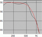
Below is a plot of a fourth order slope (red) and a woofer response I once used which was crossed using three components similar to the woofer in this thread. I would refer to that as a fourth order acoustic roll-off. It is partly due to the speakers natural mechanical and electrical filtering.
Below is a plot of a fourth order slope (red) and a woofer response I once used which was crossed using three components similar to the woofer in this thread. I would refer to that as a fourth order acoustic roll-off. It is partly due to the speakers natural mechanical and electrical filtering.
Attachments
OffGrid, that could be the way to go. I don't think I've put a crossover inside a speaker cabinet in my life. There is justification too...
Less vibration of components
Better heat dissipation for the components, and the damping material
More space for inductors to be kept separate
Less interaction between speaker magnets and iron cored inductors
Easy access for tweaking.
Disclaimer: Some high powered amps can output high enough voltages to be a shock hazard.
Last edited:
Yes, it could.. without modification.
If I were doing this I'd incorporate some or most of it into the amp. For example, if the tweeter amp has a volume control you can eliminate the series resistor and make setting the level very easy.
Then you could think about changing the input coupling capacitor to high pass the entire amp, using a small-value high quality cap working into a simple resistance load.
Sorry, one more question if you don't mind, whats the best way to calculate the wattage required for the resistors?
Hi,
Its a very good question, I am sure I dont know the answer. but incidentally it also brings about another aspect of resistor in tweeter xover circuit." where to put the tweeter attenuation resistor ? before or after the tweeter xover circuit?" some prefer to put it before and others after it. I feel it should be after, as low pass energy has already been filtered and the resistor has to dissipate only high frequency energy..
any views?
reg
prasi
It isn't possible to give a straight answer to this unfortunately.Sorry, one more question if you don't mind, whats the best way to calculate the wattage required for the resistors?
The maximum can be guessed based on the amplifier power (or the amount which you actually use). Then consider that bass voltage swings are typically much greater and any component which doesn't receive bass won't need to dissipate as much.
The tweeter crossover will restrict the power to each of the resistors below the crossover point. The C in the woofer RC will restrict the bass to the R, which won't receive treble either due to its need to flow through the series inductor. This series inductor passes the most current and its small resistance might become significant.
I gave you a formula above for estimating the maximum voltage you might see in a crossover based on what the amp is capable of swinging (in the post about capacitor voltage ratings). The power in a resistance that has a voltage across it will be: Voltage squared, divided by resistance.
Remember that crossover parts are splitting/sharing the applied voltage/current. Also remember that music is transient in nature, and if a resistor produces heat on and off (for half and half of the time), it averages to half of the heat.
Prasi, You can put the resistor closest to the tweeter. Using an L-pad (both series and parallel resistance) is good.
I covered this somewhere but I can't seem to find it now. IIRC the reason I stayed with adjusting the series resistor is because re-calculating an L-pad while tweaking is tedious.
I also did some simulations to show the way that changes to this resistance affected the rest of the circuit in a more benign way when the resistor was before the inductor. By all means, try both.
The capacitor reduces bass energy to the series resistor regardless of which side it is on.
Hi Allen and thanks for another prompt response.
I have calculated the the voltage using the formula you gave earlier (thank you), but I was more curious about the watts of the resistor. General availability range from 3W to 17W and wondered how to govern/calculate the wattage needed?
Thanks!
I have calculated the the voltage using the formula you gave earlier (thank you), but I was more curious about the watts of the resistor. General availability range from 3W to 17W and wondered how to govern/calculate the wattage needed?
Thanks!
You're welcome.
I was saying that the power rating for the resistor should be at least the voltage across it squared divided by the resistance.. that is the formula for power. But what is the voltage when used with actual music? This requires deep analysis which is beyond the scope of the excercise, but here's how I've done it in the past.
To see the maximum voltage I have connected an oscilloscope across the resistor and watched it whilst listening to a cross section of material.
The way I normally do it is by overestimating the rating and feeling the resistors after a listening session. I might be inclined then to change a tweeter resistor to a small carbon composition one (personal preference) but I don't mind sand cast resistors for bass, where my first goal is to ensure they don't become too hot to touch.
I've also done the same thing from within a simulator, which is another good way to go.
So for what it's worth, I'm not simplifying the procedure to suit this thread, I've been doing it this way for 30 years.")
I was saying that the power rating for the resistor should be at least the voltage across it squared divided by the resistance.. that is the formula for power. But what is the voltage when used with actual music? This requires deep analysis which is beyond the scope of the excercise, but here's how I've done it in the past.
To see the maximum voltage I have connected an oscilloscope across the resistor and watched it whilst listening to a cross section of material.
The way I normally do it is by overestimating the rating and feeling the resistors after a listening session. I might be inclined then to change a tweeter resistor to a small carbon composition one (personal preference) but I don't mind sand cast resistors for bass, where my first goal is to ensure they don't become too hot to touch.
I've also done the same thing from within a simulator, which is another good way to go.
So for what it's worth, I'm not simplifying the procedure to suit this thread, I've been doing it this way for 30 years.
Thanks Allen!
I'm gradually getting there now. As I mentioned earlier, and you can probably tell, electronics isn't my strong point!
Slowly but surely though I think Im getting there. Just need to put it in to practice and I'm sure it will all start to fall into place and make sense.
I notice on your circuit diagram the + and - isn't labelled, is this because it is irrelevant?
Thanks!
Good question. Phase is simple enough but a little more involved.
Consider a sinewave. The signal begins at zero then sweeps positive before dropping back through zero and going negative, then returns to zero. This is one cycle. At 1000Hz, this takes one thousandth of a second.
A cycle can be drawn as a circle with a radial line rotating 360 degrees throughout the cycle (think of a radar screen)... so the positive peak is referred to as 90°, the following zero crossing is 180° etc..
With speaker cones it is best to have both moving toward you at the same time so that their interference in the forward direction is constructive rather than destructive, which would mean you'd lose sound at the front which could appear elsewhere..like toward the ceiling for example, creating a balance issue with the direct sound and a relatively stronger reflection.
The phase difference between the drivers is of concern around the crossover, and is due to all manner of mechanical and electrical factors. It can be anywhere between 0 and 360°. Furthermore it can change in the octave either side of the crossover.
Therefore the phase slopes of the two drivers should travel alongside each other if possible and should be within 90° of each other, preferrably closer.
Changing the driver polarity can only change the phase by 180°, and getting it spot on requires measurement and crossover adjustment or speaker positional changes.
Phase applies not only to speaker cones.. every impedance, component, voltage and current has a phase component where AC is concerned.
Consider a sinewave. The signal begins at zero then sweeps positive before dropping back through zero and going negative, then returns to zero. This is one cycle. At 1000Hz, this takes one thousandth of a second.
A cycle can be drawn as a circle with a radial line rotating 360 degrees throughout the cycle (think of a radar screen)... so the positive peak is referred to as 90°, the following zero crossing is 180° etc..
With speaker cones it is best to have both moving toward you at the same time so that their interference in the forward direction is constructive rather than destructive, which would mean you'd lose sound at the front which could appear elsewhere..like toward the ceiling for example, creating a balance issue with the direct sound and a relatively stronger reflection.
The phase difference between the drivers is of concern around the crossover, and is due to all manner of mechanical and electrical factors. It can be anywhere between 0 and 360°. Furthermore it can change in the octave either side of the crossover.
Therefore the phase slopes of the two drivers should travel alongside each other if possible and should be within 90° of each other, preferrably closer.
Changing the driver polarity can only change the phase by 180°, and getting it spot on requires measurement and crossover adjustment or speaker positional changes.
speaker dave said:One comment on tweeter polarity. i.e. choosing the right polarity. Try pink noise and sit fairly close (and on the intended listening axis). Reverse the polarity reapeatedly. The better position will make the sound more integrated and will make the units sound like they merge. With the wrong choice the woofer and tweeter are perceived as separate and distinct units.
David S.
Phase applies not only to speaker cones.. every impedance, component, voltage and current has a phase component where AC is concerned.
Hi Allen, I have another question for you if you don't mind.
Just been playing around with XSim to see what effects different tweaks to different components make and wondered why the woofer impedance spike (around 60Hz) is not controlled in the same way as the tweeter, ie: putting a second resistor in parallel? Or does the spike at 60Hz not really come in to play and not a concern?
Thanks in advance!
Well, that's because the most energy in the sound lies in the deeper end. When there is already a high pass filter cutting away most of the power before the L-pad for the tweeter, you can get away using 5W or 10W resistors. With the woofer the most power is coming right into the play, so you'd better calculate half of the amplifiers power for the resistor (the other half goes through the element then). So with a 100W amplifier you'd need 50W resistor and with a 200W amplifier a 100W resistor... And anyway you'd be tossing away half of the power from your amplifier. If you really want to control the impedance spike, then you can do it with a LCR circuit.
There is normally no crossover action down at 60Hz and the peak isn't an issue for the average amp so it isn't normally necessary.
Yes, the RLC circuit is to be preferred for better correction of the peak, and for efficiency. This second reason is less of an issue with tweeters, These filters are best when measured, because peaks can be narrow and the correction is easily misaligned.
I filter the peaks on my midrange drivers (around 140Hz). The only consume a fraction of a Watt so heat isn't an issue. I have also damped them on woofers when powering from an amp with a higher output impedance so I can control the bass roll-off.
Another type of crossover, the shunt crossover, can be less sensitive to the peaks.
Thanks Tuo and Allen for the info/advice!
Like I say, Im messing around on XSim to try and get my head around the tweaking and which component does what, etc... so any points or info help a lot.
Im messing with a midrange in the sim at the moment which seems to have a peak at 6KHz, so interesting using the tweaking parameters outlined earlier
All good fun!!
- Home
- Loudspeakers
- Multi-Way
- Introduction to designing crossovers without measurement