The resistance has an effect which depends on where you use it, among other things. Used before the woofer, this resistance will waste power reducing the woofer's level slightly. Normally this effect is small and reasonably evenly spread across the woofer's range.
Any resistance in the inductor used for the tweeter will reduce the effect of the filter. Again, the effect is small.
Theory suggests it should be kept an order of magnitude (one-tenth) lower than the circuit it is a part of (as an example, one-tenth of 8 ohms). If you buy an inductor which is intended for use in a crossover, you should expect that the designer had this in mind.
Some notes for a three-way midrange. There are some special considerations although it's possible to approach the two crossovers separately first treating the mid as if it were a tweeter, then as if it were a woofer. This way it gets the treatment on both ends The relevant aspects will still be the same e.g. the low end of a mid (its impedance, response etc..) looks and acts similarly to the low end of a tweeter etc..
One thing that designers sometimes choose to do is use just a capacitor to remove the bass, after all a midrange will sometimes be more rugged in its application than a tweeter. The good thing about using a second order filter is that it will be less critical of the impedance peak that is found down at the mid driver's resonance (just a part of why I chose to use one for the tweeter). Simply put, the capacitor and inductor tend to pay more attention to each other than of just the impedance of the driver. (If measurements are involved then you have more choice in the matter).
If you happen to have a mid driver that is a few dB less sensitive than the woofer, you can try crossing them at the baffle step frequency, there is a chance it will be helpful there.
If your mid needs to be brought down in level you might consider using an L-pad. (Although the resistor layout I used for the tweeter tutorial will also work, the inductor (low-pass from the woofer tutorial) will end up being a little larger as you should add the value of the series resistor to the driver impedance just before you calculate that inductor). If you decide to use an L-pad you could use an online calculator as the maths is more involved than for the other components. Put the impedance compensation (resistor and capacitor) directly before the mid driver (if the L-pad is used to bring the mid down more than a few dB, you might even be able to dispose of this compensation, but it doesn't hurt). Put the L-pad just before the impedance compensation and don't use the other (tweeter tutorial) resistors, then put the high and low-pass filters before that.
The order of placing these two filters with each other shouldn't matter. At low frequencies the low-pass filter almost acts as if it is not there, and vice-versa with the high pass. Therefore they cannot really see each other so to speak. In reality they will interact a little and may push the mid cross points out wider than you intended, or make the middle of the range a little louder. These could be tweaked by adjusting the filter components or level resistors but there is a better suggestion to begin with.....If you keep the mid upper and lower cross points a couple of octaves or so apart, you'll have less high/low interaction.
Hope this helps.
Last edited:
Love this thread. Well done. ")
Just a quick general question, when tweaking the woofers crossover by increasing the capacitor value (in the impedence compensation network) will this have a negative effect on overall system impedence? ie: lowering it too much. I would like to ideally maintain roughly 6-8 ohms impedence overall. (woofer is rated 8 ohm)
Reason I ask is, this works really well with one of the systems I'm tweaking at the moment. But I had to increase the capacitor from 10uF to approx 22uF. Being a bit concerned, I then increased the resistor value from 6.8 ohm to 8.2 ohm thinking it will sort of counteract it without changing the sound too much. It sort of worked. (I think) Am I being too cautious?
I realise this is a very general question, but I'm just trying to get a grip on how the theory works.
Thanks
Thank you gpapag and shmb.
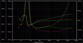
This is a good question, and I thought it would help if I showed an example. I used an example similar to the tutorial with a 6.8Ω resistor, an 8.2µF capacitor, which I then increased to 40µF which seemed extreme enough to prove a point. In all cases the grey traces are the raw driver, green is the normal case, and magenta is the extreme case.
The first image shows the effect of the impedance compensation on the driver. There are six traces, the lower three are the impedance curves that are normally shown, and the upper three are the impedance phase (which is not the same as acoustic phase). Although technically both work together, it is sometimes easier to just look at the normal impedance curve, but with regards to phase, just look at whether it is close to zero degrees or far from it meaning for example is it an easy 8 ohms to drive, or a not so easy 8 ohms to drive? If that helps.
So, the impedance drops to 4 ohms around 1kHz with the large value of capacitor, and as the phase is near zero degrees for that case, it will act similarly to a simple 4 ohm resistor, a load that most amps will handle.
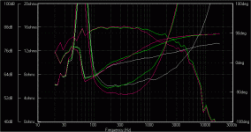
The second image shows the impedance once the 1mH inductor is added. This is the impedance that matters because it is what the amp will see. By adding the inductor, the effect of using the larger capacitor is partially hidden from the amp... the impedance is well on the rise at 1kHz and upward.
The lowest impedance here is around 5 ohms. If you look at around 600Hz, the phase is a little further from 0 degrees although still less than 90 degrees. You could take a non-technical guess that this makes it equivalent to maybe a 4 ohm load at that point.
Summarising the effect of the larger capacitor (looking at the first plot), there is little difference at the highest frequencies because all capacitors act like a short circuit at high frequencies. The effect is to act on the impedance at a lower point than before, encroaching on the lower midrange as the capacitor grows in value.
I've also shown the frequency response on the second plot (the upper two traces) for interests sake. The end result it is showing in this case, is that the greatest effect of that inductor will be above 1kHz, and the large capacitor is producing an effect both above and below 1kHz. The impedance reduction below 1kHz may be an unwanted side effect, but if it gets you the result you want then it is valid, and in this case relatively harmless.
This is a good question, and I thought it would help if I showed an example. I used an example similar to the tutorial with a 6.8Ω resistor, an 8.2µF capacitor, which I then increased to 40µF which seemed extreme enough to prove a point. In all cases the grey traces are the raw driver, green is the normal case, and magenta is the extreme case.
The first image shows the effect of the impedance compensation on the driver. There are six traces, the lower three are the impedance curves that are normally shown, and the upper three are the impedance phase (which is not the same as acoustic phase). Although technically both work together, it is sometimes easier to just look at the normal impedance curve, but with regards to phase, just look at whether it is close to zero degrees or far from it meaning for example is it an easy 8 ohms to drive, or a not so easy 8 ohms to drive? If that helps.
So, the impedance drops to 4 ohms around 1kHz with the large value of capacitor, and as the phase is near zero degrees for that case, it will act similarly to a simple 4 ohm resistor, a load that most amps will handle.
The second image shows the impedance once the 1mH inductor is added. This is the impedance that matters because it is what the amp will see. By adding the inductor, the effect of using the larger capacitor is partially hidden from the amp... the impedance is well on the rise at 1kHz and upward.
The lowest impedance here is around 5 ohms. If you look at around 600Hz, the phase is a little further from 0 degrees although still less than 90 degrees. You could take a non-technical guess that this makes it equivalent to maybe a 4 ohm load at that point.
Summarising the effect of the larger capacitor (looking at the first plot), there is little difference at the highest frequencies because all capacitors act like a short circuit at high frequencies. The effect is to act on the impedance at a lower point than before, encroaching on the lower midrange as the capacitor grows in value.
I've also shown the frequency response on the second plot (the upper two traces) for interests sake. The end result it is showing in this case, is that the greatest effect of that inductor will be above 1kHz, and the large capacitor is producing an effect both above and below 1kHz. The impedance reduction below 1kHz may be an unwanted side effect, but if it gets you the result you want then it is valid, and in this case relatively harmless.
Attachments
Thanks once again, that helps a lot.
One last thing. Will increasing the resistor value from 6.8 to about 12 ohms sort of help bring it back up a bit? I'm guessing it will, but will that have any other side effects?
I've already done this as a trial and it doesn't seem to have made as much of an audible difference as increasing the capacitor did (which is good) so I've left the 12ohm in there for now.
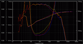
By and large, increasing the resistor will compensate like you say... but there is a catch. Impedance is complex (literally meaning it has a phase component). Generally speaking, if you overlook this you'll be OK most of the time but I thought I'd stretch the point, starting with your stated values.
If you look at the first sim attached below, yellow is 6.8Ω / 8.2µF, blue is 6.8Ω / 22µF, and red is 12Ω / 22µF (I've also changed the scales). My example will not be the same as yours but it should give a good idea of what can happen.
Both 22µF cases have a more similar frequency response than the other so that may explain why they sound more similar. The impedance is also generally more high for the 12Ω / 22µF case but this case in fact shows the lowest point of any of them.
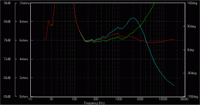
Taking it to an extreme with the second plot, I took 6.8Ω / 8.2µF, and changed the resistor to 25Ω, and to zero. If you look at the highest frequencies they are in order of the size of the resistors, but in the mid band, the higher the resistor, the lower the impedance.
If you look at the first sim attached below, yellow is 6.8Ω / 8.2µF, blue is 6.8Ω / 22µF, and red is 12Ω / 22µF (I've also changed the scales). My example will not be the same as yours but it should give a good idea of what can happen.
Both 22µF cases have a more similar frequency response than the other so that may explain why they sound more similar. The impedance is also generally more high for the 12Ω / 22µF case but this case in fact shows the lowest point of any of them.
Taking it to an extreme with the second plot, I took 6.8Ω / 8.2µF, and changed the resistor to 25Ω, and to zero. If you look at the highest frequencies they are in order of the size of the resistors, but in the mid band, the higher the resistor, the lower the impedance.
Attachments
Good effort, simplified, practical steps.Thanks Allen for the thought.
BTW, for members interested in similar methods.check this too - Practical tips loudspeaker DIY
BTW, for members interested in similar methods.check this too - Practical tips loudspeaker DIY
Thanks AllenB for a very helpful tutorial that has certainly helped me understand speaker design basics.
One qsn - which software programme are you using to model response from 2 drivers at once? I have used WinIsd and Unibox but unless I am misusing them (entirely possible!) they only model one driver at once.
Thanks
Stevenn
One qsn - which software programme are you using to model response from 2 drivers at once? I have used WinIsd and Unibox but unless I am misusing them (entirely possible!) they only model one driver at once.
Thanks
Stevenn
You're looking for crossover design software rather than box software, and it has always been a little hard to come by. For many years out of necessity I wrote and used my own software to model speakers and design crossovers. Then I got myself onto the net, but there still wasn't much. Professional packages used to be little known and quite expensive.
The program I used for the illustrations in this thread is xoversim, available at the FRD consortium where you'll find a number of good tools. xoversim only does crossovers, but it's effective and doesn't take long to get results once you learn to use it.
The *.frd file seems to be at the centre of most crossover design tools. It's a text based file that lists frequency, level and phase and it's companion file, *.zma is for speaker impedance. You can create them with sims or from real measurements.
Speaker workshop is one that I use more often nowadays. It might seem clunky and a little austere at first, but get past that and it has such a versatile manner that you can experiment freely, as opposed to just filling in all the boxes and pressing the 'give me the answer' button. Good for manipulating FRD files and making crossovers.
These days I prefer to measure as much as I can before designing a crossover, but at one point I would simulate as much as I could instead. Some people simulate their box, baffle, and even the drivers response and impedance in order to create their data files to make crossovers with. If you look through the FRD page you'll find a number of tools and it is often necessary to use several at a time to achieve the end result.
One of these is PCD (passive crossover designer). I don't have much experience with this one but it seems popular. It is based on an excel spreadsheet. It seems reasonably straightforward to use and combines some of the above functions.
For more advanced users, there is Speak available from gedlee.com which is known for being accurate particularly with modelling wave constraining devices. For existing programmers there is Akabak. It is script based, and the hardest to use but the sky's the limit. I've also used a more recent program called (if I remember correctly) 'xo', which can model crossovers taking into account a speaker's directivity and display polar plots.
With that said, I still find it near impossible to design a crossover 'properly' without continuing to write my own utility programs. The most important thing is simply to know just what you are trying to achieve and how you would like to get there.
Thanks AllenB yr reply.
I have downloaded Jeff Bagby programme and it is a little daunting... to the novice.
Main issue for me is the FDR and ZMA files, the only way i could create them was to use Unibox first and then export those files to Crossover programme. Is this correct?
Also if i have a sealed 1" Peerless 812978 tweeter, what do i put down for Vas? Programme does not work without some value here.
Thanks
This is a very good tutorial. Shure took a long time writing it.
Good you pointed out that a speaker with a 12dB lowpass over it is not necessarily dropping of 12dB/okt but more, adding the filters reaction to his natural slope. Very important information for people that are thinking of using standard x-overs which they can buy and then believe they would have a certain filterslope and they're drivers would then work together like in the book.
I still prefere meassuring during designing x-overs but not everybody will get themselves the necessary equipment and then there's still much to go wrong.
By the way hello to everybody here. I came to this forum because there's much real knowledge around here as I can see.
@Stevenn, There are many ways to create the files. A common approach would be to use the SPLTrace utility from the FRD software pages. Find a response plot from your manufacturer and turn it into a data file (this may get around your Vas problem, and in a better way as well).
You can then use another tool to extract phase information from that data file. Don't forget to include the physical separation (ie. the extra delay from the way the drivers are mounted on the baffle) when you go to use FRD data that has had a minimum phase extraction tool used on it.
I like to create new sets of data files after each significant process. This way I have snapshots I can go back to when I make a mistake, or when I change my mind on how I'll process something.
You can also create useful files by exporting a measurement. You can often export as a text file, ascii or in some human readable form. The most you may have to do is open it up in a text editor (notepad) and strip the headers (title lines) and rarely to remove commas, and to check the last line ends with enter being the last thing pressed.
You can even use the text editor to create the files.
- Home
- Loudspeakers
- Multi-Way
- Introduction to designing crossovers without measurement