copy of B&W P6 specs I could find.
B&W P6 description
Drive units One 165mm high power Cobex cone bass
One 165mm high power Kevlar cone bass/midrange
One 25mm magnetic fluid cooled metal dome high frequency
Bass alignment Twin 4th order vented box
Also described by B&W as a 3 Way 4th order vented box system
Power handling range 50W – 200W undistorted
Frequency range -6dB frequencies 26Hz – 22kHz
Frequency response 30Hz -20kHz +-2dB
Dispersion 20Hz – 10kHz Horizontal +-2dB over 60Deg arc
Vertical +-2db over 10deg arc
Sensitivity 2.83V at 1m 90dB spl
Nominal impedance 8omh (min3.5ohm)
Crossover frequencies 150Hz, 3kHz
Dimensions Height 1000mm
Width 200mm
Depth 316mm
Net Weight 18.5Kg
Hi AllenB,
The following observations are related to B&W and Sound Dynamics products because that is all I have owned.
I studied the Sound Dynamics 300Ti xovers and found most of the components were low quality and coil spacing was not good. I built outboard xovers using all air core coils, Mundorf Supreme caps and high quality non-inductive resistors. This resulted in a dramatic improvement.
I also have B&W P6s and N803s and checked out their xover design, on the B&W site. I found low quality components, and xover designs, such as electrolytic caps, iron core inductors, low quality resistors and poor coil spacing, in these and many of their other speakers lines. I must say they really stepped up to the plate with the $$$$ 800 Diamond series.
However, the P6 really stood out, as a B&W effort to meet a price point and, as an opportunity for improvement.
I thought the P6 could be improved with an outboard xover with better quality components, coil layout and midrange design changes. My latest design is attached. I would appreciate any and all feedback.
Attachments
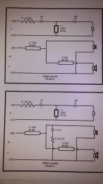
It is difficult to say anything about the result of your addition of R and C, anything would be a guess.
Direct impedance compensation is one design method but it remains an option, in fact in a measured design the impedance would usually be dealt with in a different way.. So adding it retrospectively is only going to make a change, but better or worse is not assured.
However I could guess that with some speakers what you have done here would reduce the upper (midrange) being produced by the lower drivers which could be an improvement, especially where their crossover comes close to their upper limits.
AllenB,
I really appreciate your input. What are you referring to as "the lowers drivers"? I am only expecting that the upper range of the kevlar mid range will be reduced. I don't expect there would be any change to the woofer response. Also, since these will be outboard xovers in wooden enclosures, I plan to use alligator clips to connect the components comprising the mod. This will make it easy to experiment.
I really appreciate your input. What are you referring to as "the lowers drivers"? I am only expecting that the upper range of the kevlar mid range will be reduced. I don't expect there would be any change to the woofer response. Also, since these will be outboard xovers in wooden enclosures, I plan to use alligator clips to connect the components comprising the mod. This will make it easy to experiment.
There will be a change in the signal fed to the lower bass driver.....................I am only expecting that the upper range of the kevlar mid range will be reduced. I don't expect there would be any change to the woofer response. ...............
One inductor feeds two routes.
The output into those two routes depends on the drop across that first inductor.
If you change the impedance of one of the two routes, by adding in that lower impedance RC, then you change the signal fed into the other route.
Only if the first inductor is split into two parallel sections, one dedicated to each driver can the changes to the upper bass NOT affect the lower bass.
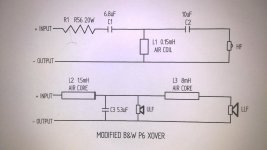
These are my latest proposed mods. Again all feedback is greatly appreciated.
The 8mH air core inductor is going to be huge and expensive for a large enough gauge to have a reasonably low DCR - consider something like an ERSE Super Q:
SuperQ Steel Core Coils | ERSE
Hi, and firstly thanks very much AllenB for a great tutorial!
I am a total newbie and been considering building for a while now. The thing that has held me back is my very limited knowledge and understanding of electronics, which I'm constantly reading up on.
Hopefully I havent missed this somewhere in the thread (apologies if I have) but once the calculations for the crossover components have been made, how do you know/calculate what the final sensitivity and nominal impedance values for the speaker are?
Thanks in advance!
Hi gracol. An inductor has a high impedance at high frequencies and a low inpedance at low frequencies. If you use one in series with a bass speaker it will have more effect on the higher bass frequencies, and will appear to disappear at the lower end. Except for the higher frequencies, the bass will behave as if there were no crossover.. sensitivity and the impedance that the amp will see are going to be similar to before.
The impedance will rise a little at the top end where the inductor is cutting the level of the sound. There is an overlap with a high frequency speaker that is using a capacitor in a more or less equal way but opposite direction. Through this overlap, the impedance is brought back down again and the sound level comes back up due to both drivers contributing at once.
So with a typical speaker the impedance is more or less the same, with some minor variations around the crossover. It is possible that the impedance would be very different if you use certain other methods of crossing. This isn't necessarily a bad thing if it is intentional.
Sensitivity is also going to remain about the same unless you intentionally reduce it. Component interactions can change sensitivity with a more complex crossover.
Hi Allen and thaks for the quick reply.
Just so that I am understanding it correctly, the sensitivity of the speaker should end up close to the sensitivity of the woofer used (ie: 87dB)?
I think I get a bit confused with the impedance. In the example you use an 8 ohm woofer and a 6 ohm tweeter the tweeter impedance then flattened to 3.75 ohms. After this stage, what would the impedance of the speaker be as a unit?
Sorry if this is a bit of a dumb question but the penny hasn't dropped yet.
Impedance may be different across the spectrum. If you played a tone at a single frequency then for that moment the impedance at other frequencies becomes irrelevant in the system.
With regards to its interaction with an amplifier, the output impedance of a typical commercial amp is designed to be around zero so that all the voltage offered will appear across a connected speaker. As a result a varying impedance shouldn't affect the response.
This is apart from the issue of drawing too much current through an amp by choosing a low impedance woofer. Also, putting resistance in series, and/or less in parallel increases the impedance though you would want to justify doing so for other reasons.
With regards to the sensitivity equalling that of the woofer, this is normally the case if you make the standard choices. ie: designing the speaker to run from one amp, choosing to bring the higher sensitivity drivers down to the lower, choosing to make the woofer the lowest...
Thanks again Allen, you're being a great help!
The AV amp I am using is rated minimum 6 ohms for speakers so I was curious/concerned how to ensure the speakers I make would be suitable.
On a different note, what power ratings, voltage and wattage, would you recommend (or what governs the power rating) of the capacitors and resistors?
Thanks!
The AV amp I am using is rated minimum 6 ohms for speakers so I was curious/concerned how to ensure the speakers I make would be suitable.
On a different note, what power ratings, voltage and wattage, would you recommend (or what governs the power rating) of the capacitors and resistors?
Thanks!
Overlapping drivers without a crossover may cause a dip in the impedance. Capacitors and inductors in parallel with a driver will become a short circuit at high and low frequencies respectively so a series component should be covering them. Normally though, 8 ohm drivers used within their normal range should give a useable impedance.Thanks again Allen, you're being a great help!
The AV amp I am using is rated minimum 6 ohms for speakers so I was curious/concerned how to ensure the speakers I make would be suitable.
On a different note, what power ratings, voltage and wattage, would you recommend (or what governs the power rating) of the capacitors and resistors?
Resistors drop a Voltage and pass a current. The product of these is the power consumption. As a guide only, 5W resistors are good to have around. In woofer circuits you might expect dissipations in the order of 1W to 20W. Tweeter circuits, perhaps 1/4W to 5W.
This is dependent on speaker sensitivity and more sensitive speakers may dissipate less. Resistors used in notch filters across the driver can sometimes be smaller. You can test this yourself by how hot they get. When they are overheated they can smell or look burned, but they may be ok and should be measured.
Voltage ratings for resistors, capacitors and inductors are there to indicate what would produce an arc which would damage them. The voltage rating for resistors and inductors is usually not a problem in a crossover for a domestic speaker.
Capacitors are marked for voltage. If you take the amplifiers power rating, multiply it by the nominal speaker impedance, take the square root of that and double the answer, you'll have a suggested minimum capacitor voltage rating.
Capacitors are marked for voltage. If you take the amplifiers power rating, multiply it by the nominal speaker impedance, take the square root of that and double the answer, you'll have a suggested minimum capacitor voltage rating.
Power in inductors and capacitors is different. Ideally they don't consume any. An inductor reacts by building a magnetic flux and a capacitor takes on an electrical charge. Both will release these again when the time is right, without losing any.
Real components do have losses though. Inductors and capacitors have a small resistance which can cause heating in them. It is best not to allow these to get hot. Inductors for crossovers can usually deal with a fair amount of power delivered to a speaker.
On another note, you should use non polarised capacitors, ie. not standard electrolytics as these need some DC to keep them biased in one direction, to protect their construction.
Last edited:
Wow, thanks Allen for such an in depth explanation. I think the penny is finally dropping.
Hopefully I'll be putting this into practice very soon then I will enjoy getting to grips with the tweaking side!?
Thanks again for your time and patience!
PS: Out of interest, is the example crossover classed as first order?
Hopefully I'll be putting this into practice very soon then I will enjoy getting to grips with the tweaking side!?
Thanks again for your time and patience!
PS: Out of interest, is the example crossover classed as first order?
Last edited:
- Home
- Loudspeakers
- Multi-Way
- Introduction to designing crossovers without measurement