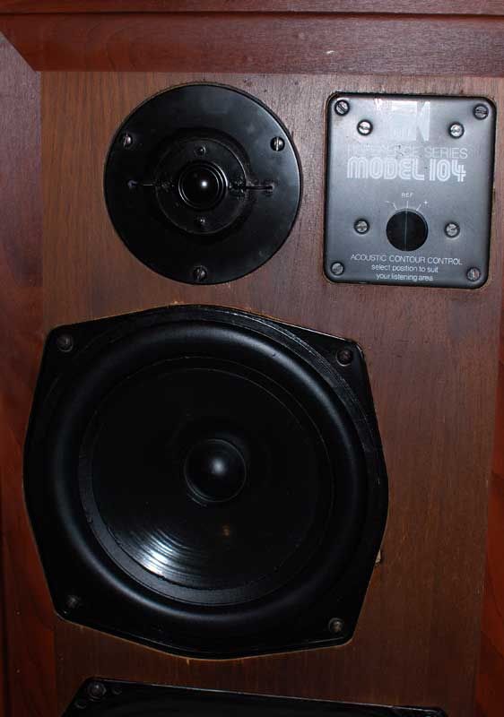
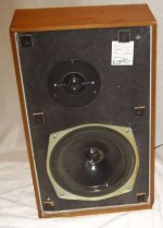
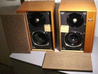
The vintage KEF104 series loud speakers still command a lot of respect today despite its age and simplicity in design. They have been many music lovers’ favorite speakers, and will continue to be much loved.
These 70s speakers have come of age and parts are no longer supported by KEF. If the speakers have spent time in humid conditions, it would require a complete overhaul for sure, after 30years in service. The crossover needs to be checked for component accuracy. And the drivers need to be checked for the correct mechanical and electrical properties.
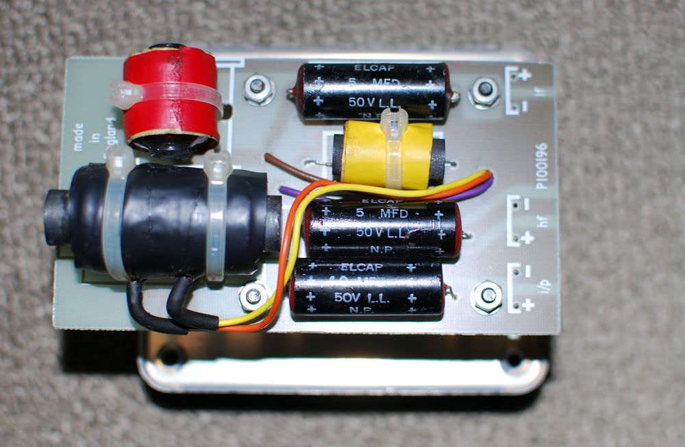
The crossover’s circuit board traces will have oxidation and corrosion after years of services. On close inspection and measurement, cross over tracks may have become thinner and pose a much higher series resistance in its path. In some cases, the corrosion may have introduced an open circuit.
The old black Elcap black capacitors on the cross over will have to go, even if kept from new. I have measured many of such capacitors. Even good meters usually could not determine the component’s correct values (not less, but strangely, much larger capacitance).
The old Alcap caps may still retain its value after 20 years. Modern capacitors can perform much better. There has been discussion on the series resistances of the cap that affects cross over design. There appear to be two schools of thoughts, and both have their merits.
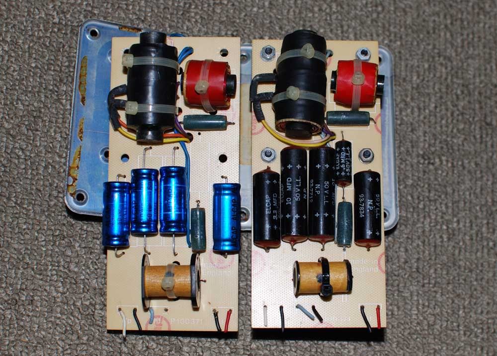
The simple, small ferrite coils may suffer from hysteresis. At high currents, or fast changing frequencies, any ferrite core will saturate magnetically and cause a non linear departure from the ideal behavior. This will manifest as distortion. The crossovers are placed very close to the driver units (behind the metal plates). Although there could be no significant magnetic coupling path, inductors are best free from strong magnetic fields. (The selector on the KEF face plate introduce contact resistances.)
The internal wiring of these speakers is thin, and made of a few tinned cores. The fact that the crossover sits at the top right of the speaker, to facilitate selection of frequency responses, require a longer wire run. This adds to the current limiting effect of the internal wiring.
As such, the original crossover is best left as is, and a new cross over based on the old design be constructed as replacement. KEF did not put together a speaker crossover from a pile of loose parts. Individual parts must have been measured, put together, and then measured again, to meet a tight specification.
Therefore, to rebuild a crossover, we must at least have a RLC meter, SPICE software to determine the correct modern equivalent for replacement. We need to understand why the crossover was designed that way, and a measurement tool to meet that specification or goal.
Having said that, we may never be able to determine the original design goals KEF had. But KEF certainly had a design budget and there always will be a spread in specification during mass production. This is not building a pair of speakers from scratch, and we can get away from using an expensive full range SPL measuring device.
ORCAD SPICE SIMULATION
This is the original KEF 104 equivalent circuit in SPICE based on KEF’s published driver data sheets. Note that for the passive components during simulation, the inductor is always made up of an inductance and a series resistance (determined by measurements). Inductors have stray capacitance but ignored. Capacitance will have series resistance but ignored. Resistors will have series inductances, but small enough to be ignored.
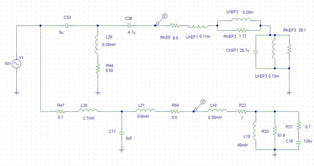
As the simulation is based on the equivalent circuit, this is only an approximation of the actual voltages appearing at the driver’s terminals. This is NOT the actual SPL output of the driver as the driver has its own non linear responses. The simulation studies the electrical characteristics in the frequency domain.
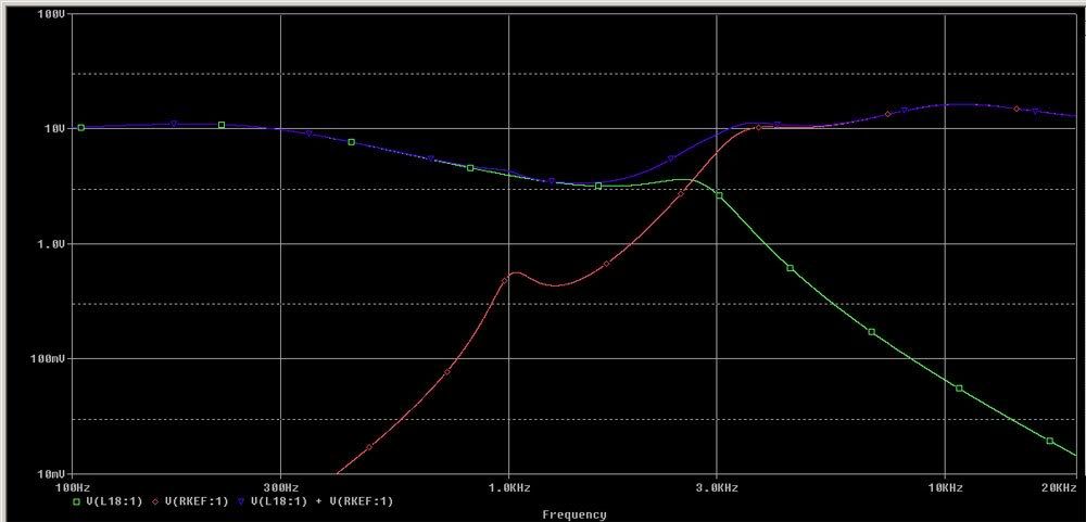
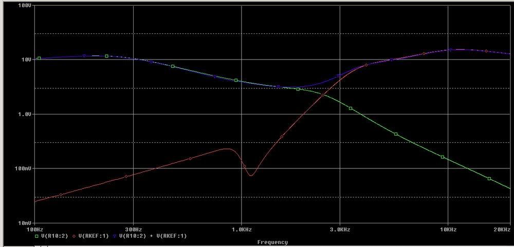
The red trace shows the voltage appearing on the T27 tweeter terminals, and the green trace the voltage appearing at the B200 bass driver terminals. The blue trace shows the summed voltage on the two drivers.
The red trace shows that there is no treatment of the natural resonance at 1.1khz for the T27A driver. There is a very slight hump at the 1kHz summed output (log scale) due to this 'resonance'. This is certainly undesirable.
The green trace shows a kink at the 2.5khz region for the bass driver.
The summed output shows that from 2.5kHz to 3kHz the transition is not smooth. However, the measured SPL of the drivers may be flat (as shown by KEF) due to the non linearity of the drivers.
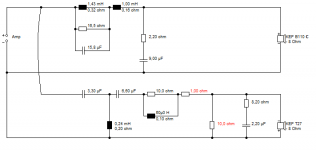
This is the KEF 104aB crossover.
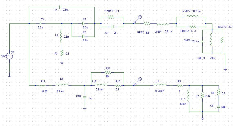
The introduction of a 0.6uf MKT type cap at the high pass, will result in a snubbing effect at the 1.1khz region, thereby attenuates the natural resonances of the T27 driver. The T27 will start to exhibit a falling SPL above the 10khz region, so the introduction of a paralleled 10uf with 3R combo will boost the output above 10khz, and flatten the resultant measured SPL.
As modern caps have lower series resistance (low ESR), this can be compensated by a very small series R, so 3R in the high pass section can be selected to measure 3.1R or 3.2R to retain that damping effect. The value printed on the component may not be the actual value of the component.
The 0.3m inductor is realized by an air cored inductor with only 0.3R dc. The original ferrite core measured 0.55R dc. The resistance of the inductor determines how deep the attenuation of the 1.1khz notch would go. At 0R the attenuation will be close to full attenuation, ie, a short circuit. However, in a real component, there is always some resistance present. It is good to use MKT type for the 0.6uf cap that has a certain series resistance.
The choice of series inductance 2.7mH needs a low series resistance and low magnetic hysteresis. Ideally, an air cored inductor will have the least distortion as there is no core saturation. However, it is hard to find one air core inductor that gives 2.7mH and lower than 0.5R in resistance. The Mundorff Alconit or ferrite series offers a coil at 0.38R with much lower distortion at high current (high current wire).
The 0.6mH is bypassed by a 10R resistor. An air core unit with 0.1R is good choice.
The simulation of the 104aB voltages with consideration of parasitic properties of the components is as follows.
At ~1.1kHz, the voltage is snubbed and prevent the T27a from seeing the offending frequency. Due to the drivers own SPL responses, anything below 1.5khz will have very little output.
At 3kHz the knee kink as in the case of 104, is removed and the transition smoothed. This would make the speaker sound less intrusive.
The B200 transition is also smoothed near the 2-2.5kHz region. The 2.5kHz region determines the perceived sound quality of the speakers.
At 2.5khz, the summed voltages appear to be smooth and no exaggeration between the 2.5khz to above 3khz. This is a marked improvement over the 104 crossover.
The boost above 10khz for the T27 remains. The output is similar to the 104 crossover.
The analysis shows that the KEF 104aB crossover is tweaked to suit the T27a characteristics. KEF's acoustic Butterworth article might not had elaborated much in these technical details. The snubbing effect appears to be a KEF special. This same designs appears in later KEF models such as the Carlton series.
As such, it is not advisable to replace the T27a with any other driver without due consideration of the high pass circuit design. It would be better to source for a pair of used T27a (measured at 6.5ohms dc resistance) than to put in a pair of Seas or Vifa unit (resonant points can be anywhere from 900Hz to 1.2kHz, and different response curves).
Real World Components
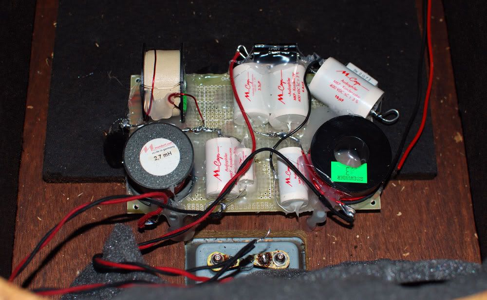
A new cross over is constructed using direct point to point connection of components. Components are secured on a FR4 board using hot glue. The final cross over is also placed near the input terminals, far away from the magnetic field of the speaker drivers.
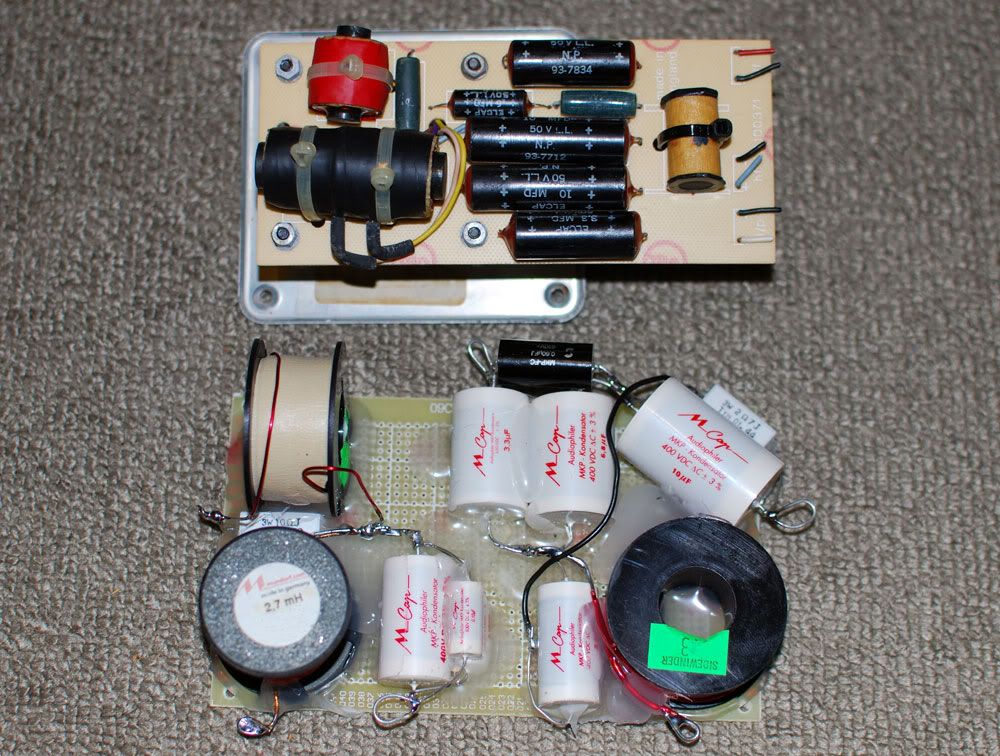
The main inductors can be of the Mundorff cored coil for its low series R and low hysteresis. The other two cores can be air core units but low series R as well. The inductors should be measured to ensure it is within 1% of the value stated.
The capacitors were chose to be Mundorff M caps (400-630V) types. The Mundorff caps are sonically superior to the Solen fast caps; both with a very similar cost. There is no need to bypass each cap with a 0.1 or 0.01uf cap, as this may result in a worse perceived high frequency. Individual caps should be measured for correct values.
The tolerance of the M cap is at 2%, at two extremes the values can be, in the case of 5uf theoretical, be 4.9u against 5.1u. This is not a lot, but we want to be accurate from the start. In the case of 10% tolerances, the deviation could be 4.5u or 5.5u, which will have significant shift in the cross over frequencies.
For internal wiring, it is recommended to use single core 18 or 16 gauge pure copper wires. As the crossover is nearer to the terminals, the overall wire run length is much reduced for the bass driver. The longer wire run for the T27a has little effect, as it favors a slightly higher series resistance. The coil inductance of the driver is much higher than the magnitude of the internal wiring. For the safety of the T27a, the 1 amp fast blow fuse should be in place.
The B200 drivers can still be sourced occasionally on Ebay UK. The drivers should have the same series resistance s and deviate very little from the spec of 7 ohm dc. Due to age, the driver coil may see loose particles in the air gap, or the coil former may be deformed due to heat. This can be checked by slightly depressing the cone and check for rubbing of coil on the magnets. The damaged coil may be repaired, but not many technicians are willing to do it these days.
The bass driver and the passive radiator should have the rubber suspension cleaned and treated by Armor All. The rubber suspension may become dry and brittle in some cases. The change in compliance of the suspension will surely change the sound.
The drivers must be installed with sealing gaskets/foams so that everything is air tight. Check by slightly depressing the main driver, and see a small following excursion on the bass radiator. If the bass radiator do not follow suit, there is leakage.
The new cross over would require at least 100 hours to break in, mainly due to the capacitors. New capacitors will always ‘sound’ closed in, compressed when new. Breaking in over 100 or even 200 hours will significantly improve the sound. Therefore, initial assessment of sound quality when the crossovers are brand new will surely result in a wrong conclusion.
With the new crossover installed with the good drivers, the speakers can sound close to what it was designed for, and even better.
Comparing the original 104 and new 104aB, the mid range is less bloated and high frequency is less piercing, even thought the 104 have higher series resistance caps. Bass is more extended and the speakers sound a few classes higher. The new 104aB sound more refined, fast, detailed and still musical. However, the 104 still holds its charm, mainly due to its coloration which many find it pleasing.
Comparing the original 104aB and the new 104aB, there are more details in the modern version with the equivalent sweetness. Bass is less muddled. The speakers appear to have a ‘lower’ sensitivity, as the volume control can be turned a few notches higher. In reality, the speaker can play music louder, with much lesser fatigue to the ears. The most significant different will be the speed of the speakers. The speaker will be able to handle transients much better. Cymbals and percussion sound more clear but less edgy.
As the crossovers continue to break in with the drivers, sonic spatial illusion becomes wickedly apparent. Separation of individual instruments is improved, and vocals become more life-like. Sound stage layering will be more distinct.
In conclusion, the old caps in these old speakers must be replaced. There is a choice of original Alcaps or Mundorff depending on personal preferences. The old inductors can be replaced by modern cores that will elevate the performance of the speakers. The internal wires are too thin and relocating the crossovers is advantageous (foregoing the facility of inductance change for equalization).
A new cross over is not expensive to build, and the old crossover can be retained for comparisons, or for display. This is a worthy upgrade; the returns are much greater than buying a new amplifier or even a new pair of modern speakers.
To fully appreciate the KEF 104aB, a high quality solid state amplifier of about 80-100Watts is recommended. Tube amplifiers either push pull or single ended above 10Watts can have good results as the speaker has decent efficiency. The source should be a good LP setup to fully demonstrate the capabilities of these classic speakers. KEF 104 can response up to 30kHz range. There are not many modern speakers that can sound as marvelous as these classics.
These 70s speakers have come of age and parts are no longer supported by KEF. If the speakers have spent time in humid conditions, it would require a complete overhaul for sure, after 30years in service. The crossover needs to be checked for component accuracy. And the drivers need to be checked for the correct mechanical and electrical properties.
The crossover’s circuit board traces will have oxidation and corrosion after years of services. On close inspection and measurement, cross over tracks may have become thinner and pose a much higher series resistance in its path. In some cases, the corrosion may have introduced an open circuit.
The old black Elcap black capacitors on the cross over will have to go, even if kept from new. I have measured many of such capacitors. Even good meters usually could not determine the component’s correct values (not less, but strangely, much larger capacitance).
The old Alcap caps may still retain its value after 20 years. Modern capacitors can perform much better. There has been discussion on the series resistances of the cap that affects cross over design. There appear to be two schools of thoughts, and both have their merits.
The simple, small ferrite coils may suffer from hysteresis. At high currents, or fast changing frequencies, any ferrite core will saturate magnetically and cause a non linear departure from the ideal behavior. This will manifest as distortion. The crossovers are placed very close to the driver units (behind the metal plates). Although there could be no significant magnetic coupling path, inductors are best free from strong magnetic fields. (The selector on the KEF face plate introduce contact resistances.)
The internal wiring of these speakers is thin, and made of a few tinned cores. The fact that the crossover sits at the top right of the speaker, to facilitate selection of frequency responses, require a longer wire run. This adds to the current limiting effect of the internal wiring.
As such, the original crossover is best left as is, and a new cross over based on the old design be constructed as replacement. KEF did not put together a speaker crossover from a pile of loose parts. Individual parts must have been measured, put together, and then measured again, to meet a tight specification.
Therefore, to rebuild a crossover, we must at least have a RLC meter, SPICE software to determine the correct modern equivalent for replacement. We need to understand why the crossover was designed that way, and a measurement tool to meet that specification or goal.
Having said that, we may never be able to determine the original design goals KEF had. But KEF certainly had a design budget and there always will be a spread in specification during mass production. This is not building a pair of speakers from scratch, and we can get away from using an expensive full range SPL measuring device.
ORCAD SPICE SIMULATION
This is the original KEF 104 equivalent circuit in SPICE based on KEF’s published driver data sheets. Note that for the passive components during simulation, the inductor is always made up of an inductance and a series resistance (determined by measurements). Inductors have stray capacitance but ignored. Capacitance will have series resistance but ignored. Resistors will have series inductances, but small enough to be ignored.
As the simulation is based on the equivalent circuit, this is only an approximation of the actual voltages appearing at the driver’s terminals. This is NOT the actual SPL output of the driver as the driver has its own non linear responses. The simulation studies the electrical characteristics in the frequency domain.
The red trace shows the voltage appearing on the T27 tweeter terminals, and the green trace the voltage appearing at the B200 bass driver terminals. The blue trace shows the summed voltage on the two drivers.
The red trace shows that there is no treatment of the natural resonance at 1.1khz for the T27A driver. There is a very slight hump at the 1kHz summed output (log scale) due to this 'resonance'. This is certainly undesirable.
The green trace shows a kink at the 2.5khz region for the bass driver.
The summed output shows that from 2.5kHz to 3kHz the transition is not smooth. However, the measured SPL of the drivers may be flat (as shown by KEF) due to the non linearity of the drivers.
This is the KEF 104aB crossover.
The introduction of a 0.6uf MKT type cap at the high pass, will result in a snubbing effect at the 1.1khz region, thereby attenuates the natural resonances of the T27 driver. The T27 will start to exhibit a falling SPL above the 10khz region, so the introduction of a paralleled 10uf with 3R combo will boost the output above 10khz, and flatten the resultant measured SPL.
As modern caps have lower series resistance (low ESR), this can be compensated by a very small series R, so 3R in the high pass section can be selected to measure 3.1R or 3.2R to retain that damping effect. The value printed on the component may not be the actual value of the component.
The 0.3m inductor is realized by an air cored inductor with only 0.3R dc. The original ferrite core measured 0.55R dc. The resistance of the inductor determines how deep the attenuation of the 1.1khz notch would go. At 0R the attenuation will be close to full attenuation, ie, a short circuit. However, in a real component, there is always some resistance present. It is good to use MKT type for the 0.6uf cap that has a certain series resistance.
The choice of series inductance 2.7mH needs a low series resistance and low magnetic hysteresis. Ideally, an air cored inductor will have the least distortion as there is no core saturation. However, it is hard to find one air core inductor that gives 2.7mH and lower than 0.5R in resistance. The Mundorff Alconit or ferrite series offers a coil at 0.38R with much lower distortion at high current (high current wire).
The 0.6mH is bypassed by a 10R resistor. An air core unit with 0.1R is good choice.
The simulation of the 104aB voltages with consideration of parasitic properties of the components is as follows.
At ~1.1kHz, the voltage is snubbed and prevent the T27a from seeing the offending frequency. Due to the drivers own SPL responses, anything below 1.5khz will have very little output.
At 3kHz the knee kink as in the case of 104, is removed and the transition smoothed. This would make the speaker sound less intrusive.
The B200 transition is also smoothed near the 2-2.5kHz region. The 2.5kHz region determines the perceived sound quality of the speakers.
At 2.5khz, the summed voltages appear to be smooth and no exaggeration between the 2.5khz to above 3khz. This is a marked improvement over the 104 crossover.
The boost above 10khz for the T27 remains. The output is similar to the 104 crossover.
The analysis shows that the KEF 104aB crossover is tweaked to suit the T27a characteristics. KEF's acoustic Butterworth article might not had elaborated much in these technical details. The snubbing effect appears to be a KEF special. This same designs appears in later KEF models such as the Carlton series.
As such, it is not advisable to replace the T27a with any other driver without due consideration of the high pass circuit design. It would be better to source for a pair of used T27a (measured at 6.5ohms dc resistance) than to put in a pair of Seas or Vifa unit (resonant points can be anywhere from 900Hz to 1.2kHz, and different response curves).
Real World Components
A new cross over is constructed using direct point to point connection of components. Components are secured on a FR4 board using hot glue. The final cross over is also placed near the input terminals, far away from the magnetic field of the speaker drivers.
The main inductors can be of the Mundorff cored coil for its low series R and low hysteresis. The other two cores can be air core units but low series R as well. The inductors should be measured to ensure it is within 1% of the value stated.
The capacitors were chose to be Mundorff M caps (400-630V) types. The Mundorff caps are sonically superior to the Solen fast caps; both with a very similar cost. There is no need to bypass each cap with a 0.1 or 0.01uf cap, as this may result in a worse perceived high frequency. Individual caps should be measured for correct values.
The tolerance of the M cap is at 2%, at two extremes the values can be, in the case of 5uf theoretical, be 4.9u against 5.1u. This is not a lot, but we want to be accurate from the start. In the case of 10% tolerances, the deviation could be 4.5u or 5.5u, which will have significant shift in the cross over frequencies.
For internal wiring, it is recommended to use single core 18 or 16 gauge pure copper wires. As the crossover is nearer to the terminals, the overall wire run length is much reduced for the bass driver. The longer wire run for the T27a has little effect, as it favors a slightly higher series resistance. The coil inductance of the driver is much higher than the magnitude of the internal wiring. For the safety of the T27a, the 1 amp fast blow fuse should be in place.
The B200 drivers can still be sourced occasionally on Ebay UK. The drivers should have the same series resistance s and deviate very little from the spec of 7 ohm dc. Due to age, the driver coil may see loose particles in the air gap, or the coil former may be deformed due to heat. This can be checked by slightly depressing the cone and check for rubbing of coil on the magnets. The damaged coil may be repaired, but not many technicians are willing to do it these days.
The bass driver and the passive radiator should have the rubber suspension cleaned and treated by Armor All. The rubber suspension may become dry and brittle in some cases. The change in compliance of the suspension will surely change the sound.
The drivers must be installed with sealing gaskets/foams so that everything is air tight. Check by slightly depressing the main driver, and see a small following excursion on the bass radiator. If the bass radiator do not follow suit, there is leakage.
The new cross over would require at least 100 hours to break in, mainly due to the capacitors. New capacitors will always ‘sound’ closed in, compressed when new. Breaking in over 100 or even 200 hours will significantly improve the sound. Therefore, initial assessment of sound quality when the crossovers are brand new will surely result in a wrong conclusion.
With the new crossover installed with the good drivers, the speakers can sound close to what it was designed for, and even better.
Comparing the original 104 and new 104aB, the mid range is less bloated and high frequency is less piercing, even thought the 104 have higher series resistance caps. Bass is more extended and the speakers sound a few classes higher. The new 104aB sound more refined, fast, detailed and still musical. However, the 104 still holds its charm, mainly due to its coloration which many find it pleasing.
Comparing the original 104aB and the new 104aB, there are more details in the modern version with the equivalent sweetness. Bass is less muddled. The speakers appear to have a ‘lower’ sensitivity, as the volume control can be turned a few notches higher. In reality, the speaker can play music louder, with much lesser fatigue to the ears. The most significant different will be the speed of the speakers. The speaker will be able to handle transients much better. Cymbals and percussion sound more clear but less edgy.
As the crossovers continue to break in with the drivers, sonic spatial illusion becomes wickedly apparent. Separation of individual instruments is improved, and vocals become more life-like. Sound stage layering will be more distinct.
In conclusion, the old caps in these old speakers must be replaced. There is a choice of original Alcaps or Mundorff depending on personal preferences. The old inductors can be replaced by modern cores that will elevate the performance of the speakers. The internal wires are too thin and relocating the crossovers is advantageous (foregoing the facility of inductance change for equalization).
A new cross over is not expensive to build, and the old crossover can be retained for comparisons, or for display. This is a worthy upgrade; the returns are much greater than buying a new amplifier or even a new pair of modern speakers.
To fully appreciate the KEF 104aB, a high quality solid state amplifier of about 80-100Watts is recommended. Tube amplifiers either push pull or single ended above 10Watts can have good results as the speaker has decent efficiency. The source should be a good LP setup to fully demonstrate the capabilities of these classic speakers. KEF 104 can response up to 30kHz range. There are not many modern speakers that can sound as marvelous as these classics.
Last edited:
Nice work and nice detailed write-up! although the objectivists (measurement crowd) wouldn't be satisfied with the lack of actual measurements of before/after.
Have owned the 104ab and thought them quite competent...just wondering if you had given any thought to bracing the cabs which are pretty cheaply constructed?...the x/over upgrades would only be one aspect of improving the overall performance.
Your observations?
Have owned the 104ab and thought them quite competent...just wondering if you had given any thought to bracing the cabs which are pretty cheaply constructed?...the x/over upgrades would only be one aspect of improving the overall performance.
Your observations?
I do not get any lift above 10 kHz using the crossover with T27?
Doctor Boar; DIY loudspeakers and HiFi
I have used plastic caps and my inducor has a slightly lower r of 0.4 ohm instead of 0.55
The bass section is an other story as I use the 1014 instead of the 1039 so I have my work cut out on that one.
Doctor Boar; DIY loudspeakers and HiFi
I have used plastic caps and my inducor has a slightly lower r of 0.4 ohm instead of 0.55
The bass section is an other story as I use the 1014 instead of the 1039 so I have my work cut out on that one.
104aB Tweeter leg
The 3.3µF 0.3mH 10µF is a classical third order high pass filter (The 104 filter) to that the 0.6µF cap was added to tame the hump at 1 kHz and the 3Ohm/10µF combo to boost the range above 10 kHz. How does this work with slightly different components in the crossover and a tweeter with 40 year old material?
For the tweeter section I have three question
1. What does the 0.6µF do for the crossover?
2. Does the 3Ohm/10µF do anything or can I remove it.
3. Can the 0.6µF be replaced by a parallell resistor in the 15-33-47 ohm range
Measurements Dayton Omnimic 0.2 m distance on axis.
The tweeter is flat on top of a baffle that is not flush mounted, just adding some masking tape around the edge of the tweeter removes the dip at 6-7 kHz so there is gains to be made.

A steep slope of 30 dB octave below 3.5 kHz
1. What does the 0.6µF do for the crossover?
2. Does the 3Ohm/10µF do anything or can I remove it.

The 0.6µF cap does help to keep the slope steep removing it (Yellow) shows this
Orange line shows the effect of removing the CR booster.
Booster effect with a more expanded scale

3. Can the 0.6µF be replaced by a parallell resistor in the 15-33-47 ohm range

Perhaps to some extent, however it also boost the >10 kHz a couple of dB a good thing. It also boosts the 3-4 kHz range 2dB that may be a good thing or not depending on the integration with the bassdriver.
The 3.3µF 0.3mH 10µF is a classical third order high pass filter (The 104 filter) to that the 0.6µF cap was added to tame the hump at 1 kHz and the 3Ohm/10µF combo to boost the range above 10 kHz. How does this work with slightly different components in the crossover and a tweeter with 40 year old material?
For the tweeter section I have three question
1. What does the 0.6µF do for the crossover?
2. Does the 3Ohm/10µF do anything or can I remove it.
3. Can the 0.6µF be replaced by a parallell resistor in the 15-33-47 ohm range
Measurements Dayton Omnimic 0.2 m distance on axis.
The tweeter is flat on top of a baffle that is not flush mounted, just adding some masking tape around the edge of the tweeter removes the dip at 6-7 kHz so there is gains to be made.
A steep slope of 30 dB octave below 3.5 kHz
1. What does the 0.6µF do for the crossover?
2. Does the 3Ohm/10µF do anything or can I remove it.
The 0.6µF cap does help to keep the slope steep removing it (Yellow) shows this
Orange line shows the effect of removing the CR booster.
Booster effect with a more expanded scale
3. Can the 0.6µF be replaced by a parallell resistor in the 15-33-47 ohm range
Perhaps to some extent, however it also boost the >10 kHz a couple of dB a good thing. It also boosts the 3-4 kHz range 2dB that may be a good thing or not depending on the integration with the bassdriver.
the 0.6uF cap , and other results ...
nimo_jon and DrBoar ,
did you use an actual 0.6uF cap for the aB modification ?
or one of the commonly available 0.56uF or 0.68uF caps ?
If you used a 0.6uF cap , please post where you obtained these from ?
I am thinking of using two 1.2uF caps connected in Series , as that reduces to 0.6uF.
*
DrBoar ,
you have some interesting results.
If I understood KEF's original explanation correctly , that 10uF//3 ohm is not a Booster ,
but is intended to reduce the output of the tweeter in the lower treble and thereby leave the 10kHz and higher region unattenuated and thus closer to the level of the lower treble ,
and that is what your measurements seem to indicate occurs.
I think its primary use is to assist with the 3rd order roll-off below 3kHz , and I see in your test 2 that it reduces resonance around 150 Hz.
I wonder what the result would be if only 10uF there and no Parallel resistor ?
The deciding factor will be whether the differences can be heard.
In your test 3 , using a resistor instead of 0.6uF there is extension of lower treble below the nominal crossover frequency ,
and the Yellow plot shows excess output at the lowest frequencies.
Which resistance is the Yellow plot , and which resistance is the Red plot ?
A resistor instead of the 0.6uF cap seems to have caused the reverse effect of what the 10uF//3 ohm achieved ...
perhaps a small resistance in Series with a slightly larger cap in the 0.6uF position may cause both the correct attenuation at low frequencies and some boost above 10kHz ?
An SP1014 B200 will not control the Passive Radiator as well as an SP1039 will ,
and the SP1014 may have a little more output above about 2kHz than the 1039.
Last edited:
alan-1-b
I used 0.22µF caps, three in parallell, that was as close as I could get.
Second graph shows
Black standard 104aB crossover
Yellow with the 0.66µF removed and a more shallow slope below 2 kHz.
Orange is with the10µF/3Ohm removed and it does nothing in my measurement as the black and orange is tracking each other well.
Presentenly I am working on an altogether different tweeter setup. While you get response all the way down to 1 kHz with the T27 it is a small 20mm dome that will struggle in the lower octaves. I have some Alnico Seas H087 domes that I will try out crossing over down at 2 kHz using 4th order LR filter. A rather unusal setup where the woofer has a smaller voice coil diameter, 1" than the tweeter has 1.5". The H087 also drops of above 10 kHz, I have to remeasure it. I then can boost the top octave with something that comes in with a 8-10 kHz filter.
I will not use my SP1014 in a 104aB enclosure (take a look on the Doorspen BC one thread, that is a homage to Spendor BC1, with bextrene cone and flimsy walls (grin)
about Kef crossover ; Other tweeters .
Hello DrBoar ,
There are 0.15uF Polypropylene caps available in some brands ,
and four in Parallel would sum to 0.6uF ,
though I'll probably use two of 1.2uF in Series to reduce to 0.6uF.
In your Graph 3 in #5 , the Expanded Scale does show sufficient difference in the lower treble to be audible.
My question was about Graph 4 in #5 ,
which resistor is the the Yellow plot and which resistor is the Red plot ?
For SEAS H087 , I would measure its Frequency Response and compare it to the KEF SP1014.
I think the SEAS will be higher output in the low treble than the SP1014 in its midrange will be after a crossover to the SP1014.
Next I would calculate an L-Pad pair of resistors for around the H087 to reduce its output ,
then I would connect a capacitor in Parallel with the Series resistor of the L-pad , in a chosen capacitance to allow the upper treble through unattenuated.
That could leave sufficient treble above 10kHz from the H087 for similar output with its lower treble.
You may get an almost flat response , and if may match the output of the SP1014 after crossover.
Then you will not need a super-tweeter
Are your plots in #7 for the SP1014 with no filter in Black ?
and with filter in Red ?
or is the Red an Off-Axis plot ?
I did not find any "Doorspen BC one" thread ,
but I did find "Dorspen" - different spelling - in your thread:
One BC, homage to a classic vintage design .
I think you will need a lot more absorptive wadding inside that enclosure.
I would use real Wool batts , though Fibreglass batts can be used.
For best result , the batts should be cut to size so to stand to full height in the enclosure , and with their open cut edges facing the back of the B200 ,
and not packed tight , but only firm enough so as to not wobble around with the rapid changes of air pressure when the B200 is playing.
I would not add a vent for use with SP1014 , because that B200 works better in a sealed box.
Your other thread about the Philips AD0160T tweeters:
Those old Philips poly dome tweeters may work better than a Kef T-27 if the Philips are still in good condition ,
and they have higher output than a T-27, so you can L-Pad them and that will cause less strain on their lower frequency excursion.
If you can open the Philips to get behind the dome , put a small piece of soft Wool or soft Cotton-wool , or a similar absorptive , cut like a small hemisphere , behind the dome.
Small enough so it does not put pressure on the back of the dome , but only touches it lightly , and of diameter to fill the space.
This will reduce the high treble resonances behind the dome.
I have done this with another brand of vintage tweeter , and I got a better measured and audible result.
Last edited:
Hello DrBoar ,
There are 0.15uF Polypropylene caps available in some brands ,
and four in Parallel would sum to 0.6uF ,
though I'll probably use two of 1.2uF in Series to reduce to 0.6uF.
In my book it works as advertised even with 3x0.22 as it gives far better tracking to the 18 dB slope
In your Graph 3 in #5 , the Expanded Scale does show sufficient difference in the lower treble to be audible.
My question was about Graph 4 in #5 ,
which resistor is the the Yellow plot and which resistor is the Red plot ?
For SEAS H087 , I would measure its Frequency Response and compare it to the KEF SP1014.
I think the SEAS will be higher output in the low treble than the SP1014 in its midrange will be after a crossover to the SP1014.
Next I would calculate an L-Pad pair of resistors for around the H087 to reduce its output ,
then I would connect a capacitor in Parallel with the Series resistor of the L-pad , in a chosen capacitance to allow the upper treble through unattenuated.
That could leave sufficient treble above 10kHz from the H087 for similar output with its lower treble.
You may get an almost flat response , and if may match the output of the SP1014 after crossover.
Then you will not need a super-tweeter
Are your plots in #7 for the SP1014 with no filter in Black ?
and with filter in Red ?
or is the Red an Off-Axis plot ?
I did not find any "Doorspen BC one" thread ,
but I did find "Dorspen" - different spelling - in your thread:
One BC, homage to a classic vintage design .
I think you will need a lot more absorptive wadding inside that enclosure.
I would use real Wool batts , though Fibreglass batts can be used.
For best result , the batts should be cut to size so to stand to full height in the enclosure , and with their open cut edges facing the back of the B200 ,
and not packed tight , but only firm enough so as to not wobble around with the rapid changes of air pressure when the B200 is playing.
I would not add a vent for use with SP1014 , because that B200 works better in a sealed box.
Your other thread about the Philips AD0160T tweeters:
Those old Philips poly dome tweeters may work better than a Kef T-27 if the Philips are still in good condition ,
and they have higher output than a T-27, so you can L-Pad them and that will cause less strain on their lower frequency excursion.
If you can open the Philips to get behind the dome , put a small piece of soft Wool or soft Cotton-wool , or a similar absorptive , cut like a small hemisphere , behind the dome.
Small enough so it does not put pressure on the back of the dome , but only touches it lightly , and of diameter to fill the space.
This will reduce the high treble resonances behind the dome.
I have done this with another brand of vintage tweeter , and I got a better measured and audible result.
That is a good idea, I have done that before. Some domes come apart well and also center well on reassmebly others not so much so I prefer to do it on domes that I can afford to lose.Thanks a lot for all the good advices

Hi there!
I found ONE speaker of this KEF Model 104aB (without the tweeter!) at the street and took it home (picture below):
I'd like to recap it using your x-over design, but also I need to know if the original tweeter is a 8 ohms.
I have a couple of tweeters. One is a Vifa 8 ohms of 95mm diameter, and the other is a Visaton 8 ohms of 104mm diameter.
The Visaton seems to be stronger, but the Vifa is, to my ears, nicer.
So, can one of them be used or replace the original one?
And VERY IMPORTANT, too: the value of the fuse and max DCv of capacitors!
Thank you very much and great thread!
An externally hosted image should be here but it was not working when we last tested it.
Last edited:
Gooodemorrgen
The impedance of the tweeter is not just a series R, you need to consider the L and C. More importantly, you need to know the sensitivity of the tweeter.
I used a Seas 22TAF to replace the fabric dome tweeter.
http://www.diyaudio.com/forums/multi-way/192077-kef-carlton-iii-resurrection-seas-22t-af.html
In theory, you can use an R-R attenuation to match any tweeter that is more sensitive to use on the original cross over. But this needs some investigation both on calculation as well as listening.
Please read the Carlton mod first. I do not know the tweeters you listed, but will be good if you find out their specifications first? Sensitivity is key.
Last edited:
nimo_jon and DrBoar ,
did you use an actual 0.6uF cap for the aB modification ?
or one of the commonly available 0.56uF or 0.68uF caps ?
If you used a 0.6uF cap , please post where you obtained these from ?
*
I used a 0.47u + 0.1uf + 0.022uf
Parallel is much better than series....
Goede morgen, Meneer!Gooodemorrgen
The impedance of the tweeter is not just a series R, you need to consider the L and C. More importantly, you need to know the sensitivity of the tweeter.
I used a Seas 22TAF to replace the fabric dome tweeter.
http://www.diyaudio.com/forums/multi-way/192077-kef-carlton-iii-resurrection-seas-22t-af.html
In theory, you can use an R-R attenuation to match any tweeter that is more sensitive to use on the original cross over. But this needs some investigation both on calculation as well as listening.
Please read the Carlton mod first. I do not know the tweeters you listed, but will be good if you find out their specifications first? Sensitivity is key.
Many thanks for the reply! I'll read the article.
The Visaton tweeter model I have is the SC 10 N.
Specs below:
Code:
Nominal power handling with high pass - 100 W (12 dB/Okt.; 4000 Hz)
Peak power handling with high pass - 150 W (12 dB/Okt.; 4000 Hz)
Nominal impedance Z - 8 Ohm
Frequency response - 1000–20000 Hz
Mean sound pressure level - 90 dB (1 W/1 m)
Opening angle (-6 dB) - 109°/8000 Hz
Resonance frequency fs - 1700 Hz
Magnetic induction - 1,3 T
Magnetic flux - 210 µWb
Height of front pole-plate - 2,5 mm
Voice coil diameter - 25 mm
Height of winding - 2 mm
Cutout diameter - 85 mm
Net weight - 0,55 kg
D.C. resistance Rdc - 6,9 Ohm
Effective piston area Sd - 5 cm²
Dynamically moved mass Mms - 0,1 g
Inductance of the voice coil L - 0,04 mHHard to tell the voltage but it could be 30 or 50V, modern electrolytics are rated higher and plastic much higher about 200 to 300V.
KEF SP1065 Crossover hifiloudspeakers.info
No fuse as far as I can see.
KEF SP1065 Crossover hifiloudspeakers.info
No fuse as far as I can see.
KEF 104aB
DrBoar, thanks!
I found good caps for replacements rated 100V. For the fuse, I've got this:
DrBoar, thanks!
I found good caps for replacements rated 100V. For the fuse, I've got this:
ColinR said:.
KEF 104's were fitted with 500mA anti surge (slow blow) fuses, replace with a smaller (400mA) quick blow fuse or do a "google" on polyswitch.
Last edited:
Nice work nimo_jon,
I am inspired now to upgrade my KEF 104 reference too; the mid-range is getting way to muffled now and the tweeter needs smoothing. I have got a question about the 5uF capacitor on the woofer: what values did you use to come to 5uF?
Thanks in advance,
Siebe
I am inspired now to upgrade my KEF 104 reference too; the mid-range is getting way to muffled now and the tweeter needs smoothing. I have got a question about the 5uF capacitor on the woofer: what values did you use to come to 5uF?
Thanks in advance,
Siebe
Siebe,
4.7uF + 0.33uF will do 5uF within 0.6% tolerance ( 5.03uF/5.00uF = 100.6%). Also some cap makers actually have 5uF film caps. AudioCap, Musicap as well as Jensen, Jupiter and Duelund.
I like the 4.7 + 0.33uF approach though as it gives you a built-in bypass cap.
Best,
Erik
4.7uF + 0.33uF will do 5uF within 0.6% tolerance ( 5.03uF/5.00uF = 100.6%). Also some cap makers actually have 5uF film caps. AudioCap, Musicap as well as Jensen, Jupiter and Duelund.
I like the 4.7 + 0.33uF approach though as it gives you a built-in bypass cap.
Best,
Erik
Wow time just went passed 5 years!
I have acquired another pair of KEF 104aB. The set was in a very sorry state. Cabinet disintegrated with some location turned in powder. One T27 fried. Two B200 surrounds started to flatten at various locations. Voice coils rubbing against magnet housing. The humid weather in Singapore was eating the speakers up.
What I am doing now:
1. Restoring the poor cabinet with putty, wood and new layer of real-wood veneer. Added brace behind the front panel for the woofers. Ready end July 18
2. Replaced the voice coils in both T27 with new replacement coils from France (EvilBay) and refill with new ferrofluid.
3. Replacing the B200 with new replacement rubber surround from Simply Speakers. Realign the voice coil to center. (I may replace the other B200 as well)
4. NO MORE PASSIVE CROSS OVERS @@!
I will be trying out a new Linkwitz–Riley active cross over. The Butterworth crossovers have a +3dB peak at 3kHz crossover frequency. Linkwitz–Riley will be flat, and less interferences at on axis listening positions. I am using a cross over board to feed two class D amplifiers (can adjust gain for the tweeters). The active cross overs are really cheap (USD$50) from Evilbay.
Should complete by end of July 18. Stay tuned
I know. Time flies. I have been here for 10 years now.
KEF were the great innovators in plastic coned loudspeakers. A tradition that is still alive and well if you follow Harbeth, Spendor, Stirling Broadcast and the like. KEF's designs mostly were derivatives of the two classic combinations below. 8" and 5" bextrene bass, 3/4" plastic tweeter.
For those who don't know much about this BBC derived style here's a fine modern Harbeth Super HL5: Harbeth Super HL5plus loudspeaker | Stereophile.com
There's no "boom and tizz" in this style. It's all about realistic reproduction of classical music and voices. Accurate monitors.
KEF were also extremely competent at crossovers for badly behaved drivers. And the old ones WERE pretty awful.
I think you'll find, Jon, that a lot of KEF designs were a very deliberate BW3. This is a good idea, IMO. There actually isn't a +3dB bump at crossover because the phase is 90 degrees. Which helps dispersion and flattens power response in 3 out of 4 directions.
You can always add an order to both arms of the crossover and get LR4. But that is a different sound. For sure, there is a lot to learn from KEF crossovers. They all have something going for them. Which is why people still revere the KEF built 11 ohm BBC LS3/5A and your KEF 104ab.
Attachments
- Home
- Loudspeakers
- Multi-Way
- KEF 104 to KEF 104aB mkII with SPICE