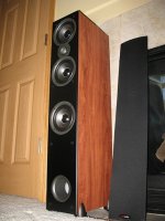
I have three woofers and one tweeter for each side. Enclosure is ~34l, ported. You might have seen my other thread about 'deciphering crossover'. Its for this speaker. I would like to see what is involved in redesigning the crossover from scratch. If you had these drivers and this volume to work with what would you do ? What do you recommend ?
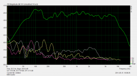
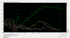
I am attaching the ZMA and FRD files for the woofer and tweeter. and also screen shots of a ungated farfield response including distortion components to give an idea of the real FR and distortion profile of these drivers.
Let me know if you need any more information in particular.
I am attaching the ZMA and FRD files for the woofer and tweeter. and also screen shots of a ungated farfield response including distortion components to give an idea of the real FR and distortion profile of these drivers.
Let me know if you need any more information in particular.
Attachments
Last edited:
FRD and ZMA - (you will have to remove the .txt extension on the files, it wouldn't attach without it).
Attachments
Last edited:
nothing series either ?
Of course you can try series crossover. Second order for example.
First filter: L=0.15mH, C=10uF (in series with 8R2)
Second filter: L=2mH, C=22uF
Three woofers in series, tweeter polarity flipped.
What about BSC ? the speakers will be up against the wall as show in the pic but the measurements were taken away from the wall. Also, I think the dip between 150-250hz is something to do with the internal(cabinet) or external(room) resonance. Dimensions of room are 15x12x9 and one of the 12' sides opens into another room.
And the nearfield response of the driver is very flat all throughout, it does not show the dip. The dip starts appearing and increasing as I move the mic 6" and more away from the driver.
Now are those textbook values or did you run the files through a XO designer ? Would PCD7 allow me to model those 3 drivers in series as "one woofer" ?
Last edited:
What about BSC ? the speakers will be up against the wall...
Now are those textbook values or did you run the files through a XO designer ? Would PCD7 allow me to model those 3 drivers in series as "one woofer" ?
BSC? Why you need it? The above values are "copy" of the original crossover (L=2mH, C=10uF). So basically it doesn't change the low end response. Effect of baffle step loss is depending on the speaker placement against the wall, so you don't really need electronic compensation.
I don't know PCD7, but been a programmer once I guess you can model the 3 drivers as one, probably with work around.
Here is I'm attaching a "better" crossover. I still use common values. The 1.8mH can be achieved from your 2mH (but you need LCR meter).
Of course I can create a better looking chart, but it is not necessary because in my experience, tuning by ears will not yield final filter corresponding to the best looking chart. What is IMPORTANT is the phase tracking shown in the chart, meaning that around the filter there is a "sweet spot".
The components values in the tweeter filter is friendly enough.
The woofer response doesn't have problematic peak (as you have measured). And being in series the cones movement is minimal.
The minor issue may be the driver placement and the internal volume if the 3 drivers do not have equal volume.
Attachments
Of course I can create a better looking chart, but it is not necessary because in my experience, tuning by ears will not yield final filter corresponding to the best looking chart. What is IMPORTANT is the phase tracking shown in the chart, meaning that around the filter there is a "sweet spot".
Correction: your data is a real time measurement of the EXACT real drivers, so what you see may be what you will exactly get.
Thanks Jay I will check it out and will post my feedback. btw, is that Speaker Workshop ? XO design is the only thing I haven't tried in SW. Perhaps I should try again.
Do you by any chance have the total system impedance ? you dont have to redo the whole thing. I was just curious to see it.
I was hoping to push the XO crossover further up (~3khz?) than what it is right now (2.3Khz) since I am actually hearing audible distortion between 1.5Kz-4Khz, and it reveals in the chart I posted in the original post as well. I want to damp that down as far as possible.
Thanks.
Yes I am sorry there are not really standard frd. Those columns are the distortion figures. You can just open it in excel and remove them as well as other header information in the file.You have 3 different amplitudes for each frequency so PCD just chooses 0db or something.
I was hoping to push the XO crossover further up (~3khz?) than what it is right now (2.3Khz) since I am actually hearing audible distortion between 1.5Kz-4Khz, and it reveals in the chart I posted in the original post as well. I want to damp that down as far as possible.
Yes, it is SW. Crossover point is 2K7. Impedance chart is attached (minimum is 4R9)
How can you be sure that the distortion came from certain frequency? And that it is individual driver issue not "blending" issue (filter problem)? Which driver is responsible? Around that frequency is usually the woofer issue, then bringing up the crossover point may create more problems?
I forgot to ask why you wanted to modify the crossover (Now you have explained). Can you post the original tweeter filter? Who knows it needs only small change to address issues such as the distortion you mentioned.
Yes, it is SW. Crossover point is 2K7. Impedance chart is attached (minimum is 4R9)
Attachments
How can you be sure that the distortion came from certain frequency? And that it is individual driver issue not "blending" issue (filter problem)? Which driver is responsible? Around that frequency is usually the woofer issue, then bringing up the crossover point may create more problems?
because I can actually hear it in that range. I happened to hear that when I was just running some step sine signals through the speaker. And the distortion measurements of the individual drivers(in my original post) indicate that this distortion is most eminent from the tweeter, and not the woofer.
The tweeter is a 2nd order high pass. L=.25mh, C=8uf and a R=0.5ohm BEFORE the XO (i.e. not on the driver side of the xo).
Now the 8uf electrolytic is bypassed by what seems to be a small film cap of 0.22uf (I am sort of assuming the value here as I can only barely read the numbers that appear to be "224J".
Yes, you're right. There is a bump on tweeter response in that range. And 224J really is 220nF.
To remove the bump the tweeter coil must be reduced. I tried 0.2mH (original is 0.25mH). To retain the original slope I inserted a 2R2 in series with the coil (I assumed coil DCR as 0.25mH). But now it is a third order with additional 10uF capacitor.
The red lines are the original. The blue lines are the modification. The phase tracking for the modified filter on simulation is better than the original.
ADD: The new crossover point is 2K7
Attachments
Last edited:
You'll be getting "floor bounce dip" with the drivers up in the air - that may be the dip at 150Hz region... you can check it by turning the box upside down, or outside and aiming it up for a test...
The baffle step plays a role too...
With three drivers one could consider two in the bass, one in the mid and then the tweeter, rather than three together.
The 'distortion' you are hearing - is it level dependent?
What is your source - have you listened to it with other speakers, or maybe with headphones with an L Pad pad on the speaker outs?
You might want to disconnect the woofer and listen only to the tweeeter.
Also then disconnect the tweeter and listen only to the woofer, see where the perception of distortion is being produced. If it is in both, perhaps the problem is elsewhere.
If it turns out to be the tweeter, replace it with a better performing unit.
I am not personally a fan of 2nd order filters... ymmv.
Impedance curve - actually check the real world impedance curve of your speaker.
I don't like the look of the posted curve where the impedance rises substantially at the xover point. NG.
Multiple order xovers may have the same filter response through the filter and a different impedance that the amp sees depending on the positioning of the components - ie. which one comes first, second... etc.
You can pretty much ignore the phase information, since ur more or less stuck with the positioning of the drivers on that baffle, and the xovers are going to do what they do, and the drivers will do the same... assuming ur x'ing over NOT at the point where one driver or the other is shifting phase dramatically, ie. ur in the passband of the driver.
Oh wait, just looked at the stock xover - where's the tweeter part?
And Polk is using the upper woofer as a "mid"...
So, you can live with it and maybe drop the probably way way too hot tweeter level down to a real world level (and hear the midrange for a change) or redesign the whole thing as a parallel xover and gain some control over the response.
If you want to get serious about speaker design you'd be better off starting from scratch with ur own driver selection, imo, and properly designed cabinets (thin tall cabs have built-in problems, fwiw).
Maybe I missed some details in the convo, but...
_-_-bear
so leave the original as is for the woofers then ?
If you don't have a problem with the sound of the woofer in the original crossover, you can consider only modifying the tweeter filter as proposed.
The other new series filter can also be considered. Bear is right, I was also a bit worried with the impedance rise around the crossover point, but that is a series filter so I'm guessing that it would be alright.
I don't think the original speaker is good, but that is what you have. Unless you want to sell them, you have to choose which crossover to be used. Many people like the sound of series crossovers. But you have to build it to find out if it is good enough or not.
speaking of phase - I realized the FRDs did not contain phase information. Is that ok for the purpose of xo design ?
Yes of course there is phase information. If not, how can it be done? May be I missed your point. I'm not agree with bear in that for me the phase is the most important parameter to build a good sounding speaker.
speaking of phase - I realized the FRDs did not contain phase information. Is that ok for the purpose of xo design ?
Phase will be relatively important in ensuring the drivers don't cancel each other near the crossover, especially as you have an MTM section. The easy way would be to take system measurements after crossover changes. A more versatile way would be to measure the phase information or use a spreadsheet to calculate minimum phase data from clean response curves, then feed it into the FRD files for use in a crossover simulator.
Probably leave the woofer sections for now and re-do the tweeter section. I'd avoid new series crossover sections for now. I'd ensure I had good measured data, including impedance and impedance phase. I'd design a tweeter resonance peak compensation network and, using the original C and L to begin with, I'd adjust the tweeter level and listen to the changes.If you had these drivers and this volume to work with what would you do ? What do you recommend ?
Yes I can leave the woofer section as is and mess with the tweeter only. At the start I was open to other configuration suggestions for the 3 woofers to see if there were any combinations that would be substantially better than the original.
btw, any difference which 2 of the 3 woofers would I 'pair' for the two paired drivers in the crossover ? The bottom 2 or the top 2 ? (bottom and top as in physical location on the baffle. please see pic of the speaker in first post).
Here's what the FRD looks like -
Frequency(Hz) Magn(dB) D2(dB) D3(dB) D4(dB)
23.893 -58.85 -10.58 5.32 5.00
24.123 -58.84 -10.41 5.41 5.30
24.356 -58.82 -10.22 5.48 5.67
24.590 -58.80 -10.02 5.54 6.11
24.827 -58.77 -9.81 5.58 6.60
25.066 -58.74 -9.58 5.61 7.14
The first two columns are Hz and db and the rest distortion db. I dont see phase degrees.
btw, any difference which 2 of the 3 woofers would I 'pair' for the two paired drivers in the crossover ? The bottom 2 or the top 2 ? (bottom and top as in physical location on the baffle. please see pic of the speaker in first post).
Yes of course there is phase information. If not, how can it be done? May be I missed your point.
Here's what the FRD looks like -
Frequency(Hz) Magn(dB) D2(dB) D3(dB) D4(dB)
23.893 -58.85 -10.58 5.32 5.00
24.123 -58.84 -10.41 5.41 5.30
24.356 -58.82 -10.22 5.48 5.67
24.590 -58.80 -10.02 5.54 6.11
24.827 -58.77 -9.81 5.58 6.60
25.066 -58.74 -9.58 5.61 7.14
The first two columns are Hz and db and the rest distortion db. I dont see phase degrees.
Pairing the woofers around the tweeter might have been used to improve the vertical dispersion around the tweeter. Using three woofers all up may have been useful to reduce floor and ceiling bounce. If it were me, when it came to adjusting the woofer crossover I would first start with the inductance only to change the crossover frequency or to match to the tweeter as required.
Your FRD file may be more useful with only three columns...frequency, magnitude, phase. Until you can get phase data (or simulate minimum phase data at least) I would at least zero out the third column and delete the 4th and 5th.
Your FRD file may be more useful with only three columns...frequency, magnitude, phase. Until you can get phase data (or simulate minimum phase data at least) I would at least zero out the third column and delete the 4th and 5th.
- Status
- This old topic is closed. If you want to reopen this topic, contact a moderator using the "Report Post" button.
- Home
- Loudspeakers
- Multi-Way
- Inviting design ideas for these drivers and cabinet (files and pics inside)