There's an Evans Capacitor company in Providence, RI that has a product called Mega Cap.
Thanks for the info. I went through their site and found nothing similar.
Evans Capacitor Company -- High Energy Tantalum Capacitors
There is also TDK that makes a Mega Cap. I found nothing similar on their site as well.
TDK Corporation - Americas
Im going to try sending off an email to both
There's an Evans Capacitor company in Providence, RI that has a product called Mega Cap.
I wanna upgrade the caps on my crossover In my Energy speakers.I wanna get a rough idea of the quality of these caps. I was told by a local speaker guy that their probably bulk caps and not worth much.
any film is way better than the electros - polypropylene is one of the better film dielectrics - I would say these are the last caps to replace on that XO board even if you believe "capacitor sound" is in any way significant compared to driver quality and actual XO filter response
I wanna upgrade the caps on my crossover In my Energy speakers.I wanna get a rough idea of the quality of these caps. I was told by a local speaker guy that their probably bulk caps and not worth much.
I'll update the energy xo upgrade thread soon... but let me tell you they are completely different speakers after replacing all the signal caps in the mid/highs! (in addition to the signal resistors & inductors)
you don't have to "squint" to hear the diffs, they are utterly different, I am very excited about it-- they might as well *be* another set of speakers for how fundamentally the sound changed
http://www.diyaudio.com/forums/multi-way/184297-energy-veritas-2-2i-crossover-project.html
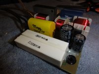
in the attached pic, the two 5uF signal caps to the tweeter are replaced, and the single 6uF cap for the midrange, underneath those the resistors are also replaced with mundorf supremes
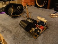
the other pic shows it before the tweeter caps were on, you can see the resistors
Attachments
Last edited:
any film is way better than the electros - polypropylene is one of the better film dielectrics - I would say these are the last caps to replace on that XO board even if you believe "capacitor sound" is in any way significant compared to driver quality and actual XO filter response
The electolytic caps are not in the signal path, the only point i'd see to replace them is for reliability, electrolytics tend to wear out.
The capacitor sound ended up being *very* significant on these speakers.
The difference in sound is hard to describe, it's like the original caps emphasised all the fine details, so they got in their own way-- now that emphasis is gone, and you can hear far *more* detail! -- also the sound is freakishly juicy/fluid, the original caps are hashy/grainy compared to these, and I thought *those* were fluid until I heard these! also, now I know what a 3d sound stage sounds like! before it was layered & with depth, but each layer was 2d!
Last edited:
The electolytic caps are not in the signal path
Where are they, then?
Where are they, then?
in parallel with the speaker driver, and also in this case, in parallel with one of the poly caps... so far less influence on the sound, but yeah there's is maybe a little, you can replace them & listen for diffs
i mis-spoke with "in signal path", meant to say not in series with the speaker driver
Last edited:
Thanks. It's often not well understood that shunt components are just as much part of the "signal path" as series components. This is a consequence of first principles (conservation).
When doing cap changeouts, be EXTRA careful that you maintain ESR- in a well-designed crossover, this is taken into account, so the crossover slopes and levels can be negatively affected. Polyprop for electrolytic will usually require a small series resistance.
When doing cap changeouts, be EXTRA careful that you maintain ESR- in a well-designed crossover, this is taken into account, so the crossover slopes and levels can be negatively affected. Polyprop for electrolytic will usually require a small series resistance.
Thanks. It's often not well understood that shunt components are just as much part of the "signal path" as series components. This is a consequence of first principles (conservation).
When doing cap changeouts, be EXTRA careful that you maintain ESR- in a well-designed crossover, this is taken into account, so the crossover slopes and levels can be negatively affected. Polyprop for electrolytic will usually require a small series resistance.
cool, I was wondering that for my energy c2 project, i changed an electrolytic with a poly (far bigger)
with the veritas crossover, i'm leaving the orig electrolytic caps
Last edited:
Thanks. It's often not well understood that shunt components are just as much part of the "signal path" as series components. This is a consequence of first principles (conservation).
SY, am I incorrect with this statement? -->
in parallel with the speaker driver, and also in this case, in parallel with one of the poly caps... so far less influence on the sound, but yeah there's is maybe a little, you can replace them & listen for diffs
-->
how much do *shunt* components influence the sound? I'm ignoring them (keeping the original parts) in my veritas project--
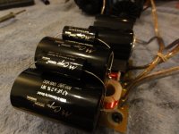
also for reference pics, see this post: http://www.diyaudio.com/forums/multi-way/185178-polypropylene-mega-cap.html#post2505844 --> you can see the to untouched electrolytics
and this for parts I changed: http://www.diyaudio.com/forums/mult...tas-2-2i-crossover-project-6.html#post2506070
Last edited:
how much do *shunt* components influence the sound? I'm ignoring them (keeping the original parts) in my veritas project--
As much as series components.
You'll need a capacitance bridge to measure ESR- or you could see if you can dig up the cap manufacturer's specs (a better way since who knows what's happened to those caps over time). Failing that, you could contact the speaker's maker- they might be able to answer that for you.
how can you measure ESR, can you use a multimeter? prob a noob question")
Here's what someone else wrote about measureing ESR at another forum:
"A WT3 reads out resistance (DCR) and inductance (@ either 1kHz or 10kHz-for tweeters mostly) directly. To measure a capacitor, just measure the impedance @ 1000 Hz, and divide into 159."
Obviously, to do what he wrote means you need a woofer tester 3. A WT2 will also measure ESR.
Also, ESR meters are available on the WWW for <$100.
Last edited:
...woofer tester 3. A WT2 will also measure ESR.
I would always consider WT2 (the original) over the WT3 (the cheap clone)
dave
cool, I was wondering that for my energy c2 project, i changed an electrolytic with a poly (far bigger)
with the veritas crossover, i'm leaving the orig electrolytic caps
What SY said is true, however the in circuit resistance of components is more applicable to inductors than it is to electrolytic capacitors. A good NP electrolytic will have some, but not a heck of lot of ESR. However a large air cored inductor will definitely have several tenths of ohms resistance. If you look at the better software for designing crossovers you'll see they model (schematics) with the inductor resistance included too.
I wanna upgrade the caps on my crossover In my Energy speakers.I wanna get a rough idea of the quality of these caps. I was told by a local speaker guy that their probably bulk caps and not worth much.
Like others have told you, film caps are almost always better sounding than Non Polarized electrolytics in crossover circuits.
Loudspeaker manufacturers will use electrolytics primarily to save on cost (money) and also because they are physically smaller and easier to fit into a compact circuit board.
You don't need to waste your time measuring the ESR of polypropylene caps. But a cap meter would come in handy for measuring their absolute component value. Budget components are spec'd at a lower tolerance.
Last edited:
Here's what someone else wrote about measureing ESR at another forum:
"A WT3 reads out resistance (DCR) and inductance (@ either 1kHz or 10kHz-for tweeters mostly) directly. To measure a capacitor, just measure the impedance @ 1000 Hz, and divide into 159."
ESR for NPE caps are usually specified at 120Hz. ESR is frequency-dependent, so what you really need to know is the ESR at the crossover frequency. ESR is also expressed in terms of the Dissipation Factor, which is usually stated as a constant, although it varies a fair amount with temperature and frequency.
As long as the DF is less than 10% the ESR will not have much effect on the crossover behavior. I believe that some of the early NPE capacitors had fairly high dissipation factors (10-15%), so maybe you need to add resistance, but probably not--depends on your cap and the driver impedance. Newer "audio-grade" NPE's are rated at 3 to 5% DF, which is nowhere near as good as a film cap, but it is not enough to have a significant affect on the crossover response.
The test code at the link will model the effect of the NPE ESR. Use the Crossover module and try setting the DF to 10%. There is a checkbox for "turning on and off" the ESR from the NPE in the circuit model. With 10% DF caps and a 4-pole crossover, the response can be affected by as much as 2db for 8-ohm drivers. However, with a simple 2-pole crossover using NPE parts, the crossover response is within .5db (too hard to read exactly from the chart--but it is close to "negligible").
http://www.audiodevelopers.com/Software/PSD_NPE.zip
The code takes a while to install on some machines because it has to update the .NET framework to version 4.0 and it installs a lot of components for Compact SQL. But it is all Microsoft Visual Studio stuff--nothing else.
Last edited:
- Status
- This old topic is closed. If you want to reopen this topic, contact a moderator using the "Report Post" button.
- Home
- Loudspeakers
- Multi-Way
- Polypropylene Mega Cap??