Hi guys, thanks again for your input, all very helpful!
With regard to selection of Q filters. Is there any negative impact if i were to use a mixture of say a L-R (Q=0.5) for the lowpass on the midrange @ 3khz cutoff and a Butterworth (Q=0.7) for the tweeter @ 3.2khz cutoff?
This is a hypothetical question really but would be interested to hear peoples thoughts.
Assume the woofer lowpass and mid highpass are both L-R @ 0.5Q.
Assume all networks are still 2nd order.
The two signals cant be made to be in phase woth each other over much of the crossover region. Hence you will have the signal canceling in some regions. This means off axis where the phase is different due to path length you will have more signal. This can lead to too much power in the room at this frequency. However this can sometimes be balanced against the beamming you tend to get at the top of the mid range driver to fill in the lost energy as you transfer over to the tweeter that will typically be radiating into a full 1/2 pi at the bottom end of its response.
You would probably have to balance this by ear as the room average measurements would be very difficult to make.
Regards,
Andrew
You would probably have to balance this by ear as the room average measurements would be very difficult to make.
Regards,
Andrew
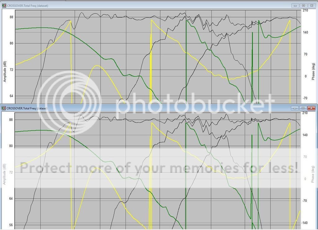
Hi Andrew. So If i have understood you correctly, what youre saying is that if i were to use a LR Q of 0.5 for the lowpass on the midrange driver and a Butterworth Q of 0.7 for the highpass on the tweeter, I would end up with the drivers slightly out of phase. Is that correct?
The phase diagram in the simulation is almost identical comparing this to if I have both drivers with a LR Q of 0.5 (Shown below where the LR tweeter network is top, Butterworth bottom).
Is this because the effect will be primarily off axis and this simulation is on axis?
 [/IMG]
The phase diagram in the simulation is almost identical comparing this to if I have both drivers with a LR Q of 0.5 (Shown below where the LR tweeter network is top, Butterworth bottom).
Is this because the effect will be primarily off axis and this simulation is on axis?
How are you calculating the Q of the filter because the bottom one looke more like what I remember. But neither design looks like the drivers are in phase through the crossover region the phase plots should overlay each other as far as possible. I am also unclear why the yellow plot turns back on itself in the HF region.
Regards,
Andrew
Regards,
Andrew
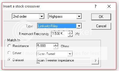
I am calculating the Q of the filter using speaker workshop to perform the actual calculation. But In terms of input, I specify the crossover frequency and the drivers impedance curve (or impedance curve with a zobel where relevant) and it calculates a relevant filter with a specified Q.
The first image below is the input dialog box for a crossover network. The second image is the full display of my actual crossover that is shown in my previous post #16
The only issue with this crossover is that I did not specifically calculate a Q, but rather just designed as I went along to match the phase diagrams and get a flat FR. The actual Q values for each filter vary from 0.6-1.0.
Ok, I havent used speaker workshop enought to know this for sure but I think its calculating a theoretical electrical response. If this is the case it combines eith the acoustic response of the speaker and will give you a completely different Q for the combined electroacoustic response.
It is this combined response that needs to match the Q of the desired filter to achine a in phase response through the crossover region.
So your approach of optimising till the responses are in phase through as much of the xover region as possible is much better than using a theoretical electrical Q.
Regards,
Andrew
I think you have done a great job showing the drivers can work in this application. The next step is to buy the drivers install them and measure the response for all as mounted in the box running full range. Measure the impedance sweeps and import your actual measured frd and zma files into the sim and tweak one more time to get actual xo values to order. That will get you perfect theory vs measured result in the end.
Don't forget to measure the combined drivers in combination (tweet + mid) and (tweet + woofer) and (mid + woofer) and individually so you can calculate acoustic centers offset for proper time and phase alignment.
Don't forget to measure the combined drivers in combination (tweet + mid) and (tweet + woofer) and (mid + woofer) and individually so you can calculate acoustic centers offset for proper time and phase alignment.
Last edited:
Ok thanks again guys. I dont have measuring equipment as it stands, so I plan to build them and test by ear initially. I may look into renting equipment to measure their response at a later date to determine how they actually compare to the theory and adjust if/where required.
I have settled on a final design which also includes zobels to flatten impedance of the drivers. In this final design the theoretical FR is +-1dB and I have finally managed to get the phase of the drivers almost perfectly aligned as well and they all roll off quickly and evenly helping to reduce overlap. I notice on the woofers a clear comb filtering effect when I input their offset in speaker workshop but this happens from 1khz upwards and I have crossed them over quite low so hopefully this effect will not be significantly audible.
This will be my last post on this thread and I will create a new thread which will be a build log of the final design and I intend to report the results there too for anyone interested. I will link this thread once I open it.
Finally, thanks again to everyone for your help which has allowed me to complete this theoretical simulation, I much appreciate it.
Cheers,
Andrew.
Hi,
There is a free measurement system and you can make a usable mic very cheaply, see below. The mic will also work with the measurement part of speaker workshop and there are instructions in the help system on how to make impedance measurements with a test resistance.
HOLM Acoustics
Website for Holm impulse above its free.
Wm 61a is the part number for a measurement microphone capsule. They are now obsolete but you can still get them and there are loads of guides on how to make a quite good microphone for about £5 with one of these. Search ebay for a supplier of small quantaties.
Or just by a mic from Holm or Beringer make an OK one as well.
Regards,
Andrew
Sorry link didnt work
HOLM Acoustics
You really will learn allot by measuring as well as using simulation
Andrew
HOLM Acoustics
You really will learn allot by measuring as well as using simulation
Andrew
Thanks guys, you have persuaded me to buy/build some measuring equipment now purely for my own interest so I can see how the simulation compares to the real world results. I have already ordered my crossover components which haven't come in very expensive so my plan is to build as is from simulation data, then compare the measured results with that of the simulation once I've obtained proper measuring equipment. With a bit of luck I'm hoping to only need a few minor tweaks but whatever the outcome, I will update in a new thread in due course!
Cheers,
Andrew.
Cheers,
Andrew.
Hi Andrew, if you haven't done so already, create a target for your crossover network. If you are aiming for 2nd order LR at 3.5K then that is what you put in as a target (and the db level it should be at). That will give you a target you can graph and tweak your network to match it. You may not need a 2nd order electrical to match that accoustic target.
Another tip wiith speaker workshop, if you model High pass and low pass separately, you can use the optimiser to try to automatically match that target curve. This takes a bit of practice, working out which range to optimize over (and sometimes does not work out well) but it is a powerful feature. You can combine a lowpass and highpass curve to see what the combined result will be.
Tony.
I've always been curious about these. If you don't mind my asking, what kind of distortion measuring performance is attainable from them below 100dB?Don't forget REW software. Also free and visually easier to use and see plots. Calibrated mics are about $70. I use UMIK-1 and UMM-6 USB mics.
Dear Companions perhaps this is not the exactly place for my question, but any way I´ll take the chance .MY IMP/MLSA is out of order, the software is corrupted I use it among other things to measure T.Small speaker parameters, I´ve purchased from a known sellers a cheap device "DaytonV2" but the device only deliver "small" signal data there is a debate between High and Small signal data does somebody would tell me if that small data will be proper for High-End Speaker design?..
Hi Andrew, where did you get you cabinets made as I am looking for someone to make some for me?
BlackMonk, Theil Small parameters are not necessarily small singal parameters in the way you seem to be implying, they are called Theil Small parameters after the last names of the two researchers who origionally developed the speaker model that they are derived from.
For a high end speaker design you want the speaker to be in its mormal operating range when taking the measurements. This would normally be in the 1W to 5W region.
Regards,
Andrew
Hi Andrew, I had the cabinets made by Wilmslow audio. I provided drawings although they can do this themselves and it is all included in the price. Mine were just flat pack CNC machined, but the quality is very good!
Also I have started a new build thread which will be updated as I go along. For anyone interested, here is the link")
http://www.diyaudio.com/forums/multi-way/283032-scanspeak-morel-3-way.html#post4529818
Also I have started a new build thread which will be updated as I go along. For anyone interested, here is the link
http://www.diyaudio.com/forums/multi-way/283032-scanspeak-morel-3-way.html#post4529818
Dear Companion Andrew thanks for your answer.
Sorry but I did not understand your answer do you mind that the device that I purchased,the Dayton V2 is unuseful, and I should put it in the basket, and I should forget about the device (because small signals are, (I repeat "unuseful", meaning all the data that produces is erroneus?.
Sorry but I did not understand your answer do you mind that the device that I purchased,the Dayton V2 is unuseful, and I should put it in the basket, and I should forget about the device (because small signals are, (I repeat "unuseful", meaning all the data that produces is erroneus?.
- Status
- This old topic is closed. If you want to reopen this topic, contact a moderator using the "Report Post" button.
- Home
- Loudspeakers
- Multi-Way
- Final Speaker design before driver purchase - please comment!!