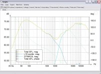
I'm trying to learn LSPCAD, so I wanted to replicate a well documented design. I figure if I can get the response graphs to look the same or similar to John Krutke's simulations, it would at least show that I'm going in th right direction.
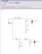
I took Zaphs L18/27TBFCG Design, and drew it out exactly as he has it. I'm using the frequency response files for these drivers that John himself posted.
The resulting graphs look terrible. Can anyone point me in the right direction. What am I doing wrong?
I took Zaphs L18/27TBFCG Design, and drew it out exactly as he has it. I'm using the frequency response files for these drivers that John himself posted.
The resulting graphs look terrible. Can anyone point me in the right direction. What am I doing wrong?
Attachments
Well, I never used LspCAD but I tried a couple similar programs.
First, what you doing wrong is using the freq response from internet.
You have to use freq response from drivers measured in that enclosure, I think anyway.
I get an impression that getting good results from LspCAD is about as hard as to learn how to design good loudspeakers, so keep up the good work!
Maybe some more experienced people will shed some light on this...
Also I trust Zaph uses some different software, maybe if you used that one you get different results?
o.0
- Status
- This old topic is closed. If you want to reopen this topic, contact a moderator using the "Report Post" button.