I am aware that if you invert one driver, wire it in opposite phase, and place it in the same plane as another driver, you will cancel even order distortion.
This is exactly what Linkwitz uses for the OB bass section of the Orion with the XLS woofers.
However, does it actually produce a notable difference or is it simply good in theory? I've heard the difference is subtle, but with OB woofers the improved distortion performance may be non-negligible. I'm debating whether it would be worth it in the midbass and upper bass. Aesthetically, it is a very undesirable option.
Thanks,
Thadman
Noteable? yes
Subtle? no way!
I run all drivers except the tweeter (there's only one...) push-pull, even the midranges in my 4-way system.
The difference is in my opinion very obvious measurement-wise. Subjectively, there is a noteable difference - it sounds cleaner, tighter, better defined.
Subtle? no way!
I run all drivers except the tweeter (there's only one...) push-pull, even the midranges in my 4-way system.
The difference is in my opinion very obvious measurement-wise. Subjectively, there is a noteable difference - it sounds cleaner, tighter, better defined.
...
I've heard the difference is subtle, but with OB woofers the improved distortion performance may be non-negligible. I'm debating whether it would be worth it in the midbass and upper bass. Aesthetically, it is a very undesirable option.
...
So, what's the debating?

You can try it yourself any time after the baffle holes are cut. The effort is only turning several screws, isn't it?
I won't bother myself. I can't stand the looks anyway. Some drivers do have handsome rear view - those functional beauties, but if this is the case, I'd like to show all drivers with the same side, and then it's still no benefit in distortion cancelling.
OTOH, the force cancellation in W-baffle type of mounting is indeed significant. It supresses vibration very effectively. Then again, it's not pretty, either.
Do you consider mounting the drivers with swings?
It can be beatifully done and very little vibration issue. As to the distorion of the drivers themselves, just never mind.Don`t we have to consider two rather different cases?
First the "bass" region (up to 500 Hz): In this region I have never seen a difference in frequency response between front and back of a driver. But you can get different response if the front and back volumes of the housing are as different as in a W frame a la Linkwitz. I would prefer a symmetrical position of the drivers in the "Ripole" style.
If you really want to cancel even order distortion, only the H configuration would do that perfectly - but without impulse compensation.
Second the region above 500 Hz: When drivers develop different radiation patterns to the front and rear, it is always a good idea to mount paired drivers in opposite directions. Whether the notion of "sounds better" is the result of distortion compensation or of better symmetry in the frequeny response (or the combination of both), I would not dare to judge.
Rudolf
I think I saw a post by Linkwitz somewhere where he said he's measured a 15dB reduction in distortion by using the reversed mounting technique on the woofers. The new Orion 4.0 prototype uses a different mounting technique to achieve the same thing, I think.
http://www.diyaudio.com/forums/multi-way/123512-ultimate-ob-gallery-39.html#post2337403
http://www.diyaudio.com/forums/multi-way/123512-ultimate-ob-gallery-39.html#post2337403
I favor a speaker's front cone sound over the rear cone, and I do not inverse mount woofer or midrange speakers. A W-frame with counter mass vibration balancing is the only execption for me. Personally, I still favor the sound of an H-frame with front facing woofers despite higher vibration problems then a W-frame, but H-frames demand isolated mounting of midrange and woofers.
I noticed that Linkwitz's latest Orion 4 uses a horizontal orientation W-frame instead of the previous H-frame. This is an engineering decision to accept the gravity cone sag on horizontal speakers in order to remove cabinet frame vibrations.
Many woofers and midranges employ some type of rear cone and/or motor air venting for cooling and/or to vent the dust cap air. I can hear this air noise, and so I send it to the back wave where is it less noticable. Most speakers are designed for closed box operation where the vent huffing can be contained. Speakers with phase plugs, even large woofers like the Lambda TD15D, often have the lowest air noise.
Attachments
What Rudolf said.
Midbass and above, yes. Upper bass, maybe, depending on driver selection and what exactly upper bass means to you. My solution was BG Radia Neo10s. Real nice drivers, even with their vertical directivity limitations.I'm debating whether it would be worth it in the midbass and upper bass.
I have 4 NS15s I would like to use for dipole midbass. I have been following StigErik's thread as well as a few others and would like to achieve something similar.
However, I'm not sure how high in frequency they should be taken. The primary cone resonance is ~2.2KHz, which corresponds with the first impedance aberration. Frequency response is flat to 500Hz and is down 6dB by 1KHz. Distortion decreases with frequency up until about 500Hz (-55dB), but is below 1% until ~8KHz.
http://www.aurasound.com/public/pdf/NS15-992-4A.pdf
My intuition is suggesting a ~2nd order FIR filter at ~150Hz.
How would you "suspend" these woofers? I was thinking of using a vertical arrangement with the lower woofer inverted. These really are beautiful woofers, so it should be relatively aesthetically pleasing. Could I mount the woofers to a minimalist frame and suspend this? I have a feeling their frames should be coupled in order to maximize harmonic distortion cancellation.
I'd like to incorporate them into a linear phase multi-way system. A Duelund XO with a=2 could be nice. If the interdriver spacing is minized, a=sqrt(3) could be very interesting.
I've been trying to understand the minimum driver layout constraints in order to be able to assume quasi constant directivity. If we force the lower range driver to be -20dB as its interdriver spacing approaches distance/wavelength=.5, we might get some interesting results. Any thoughts?
Honestly though, a 3-way simply will not be able to work without significant sacrifices if constant directivity dipole behavior is desired. A 5-way could be very interesting, but a 4-way would probably be much easier (monopole subwoofer <50Hz would make it a 4+1 or 5+1 way). Has anybody used a higher order Duelund?
Also, I'd like to avoid symmetrical driver layouts (ie WMTMW, MTM, etc). Waves expand as spheres. If a linesource is used, the wavefront will distort as it transforms into a spherical wavefront in the nearfield. If we assume the listener is in the far field, then by going with a symmetrical layout we have reduced the amount of possible surface area within the plane where the waves sum constructively.
Between ~800Hz and ~1.6KHz, human hearing transitions from ITD to ILD. As a result, we might compromise (ie minor lobes) the response above 4KHz in order to allow for some design flexibility below 1.6KHz by extending the response of an upper midrange driver into the lower treble. John K appears to have achieved success in using this technique in his Nao Note loudspeaker.
Phase is not that significant above 4KHz, so a BG Neo3 might be added as a supertweeter. The SS 10F will afford the opportunity for 1 wavelength driver spacing at ~3.8-4KHz. If we machine the drivers frame off and mount it by the magnet, we might be able to push this up to ~4.2-4.5KHz.
I have access to a machine shop, so driver modifications and metal fabrication are possible. A custom aluminum dipole waveguide would be within reason. I'm not sure if a torus (controlled response) would be superior to no baffle (closer spacing)? I assume there is some ratio between the ID/OD of the torus and the driver diameter which minimizes the dipole peak, of course the depth of the waveguide should be <1/4WL at the highest frequency.
Push/Pull NS15 --> W22EX --> W15CH --> SS 10F ------> BG Neo3
A waveguide for the SS 10F could be interesting since it will assume a relatively wide bandwidth. John K seems to think so. However, I'm not sure how to optimize the waveguide. The velocity distribution at the throat must be known in order to determine and optimize the far field response. Any thoughts on how to estimate or measure this? I'd assume it will be non-trivial considering the modal contributions of the cone have to be considered and the fiberglass cone isn't exactly homogeneous.
Push/Pull NS15 --> TD15M --> W22EX? --> SS10F w/ WG ------> BG Neo3 ???
I have a pair of TD15M Apollo lower midrange drivers, but they don't quite fit into this constant directivity dipole design if the NS15s are used. However, I'd really like to incorporate it (linear phase must be satisfied) into the system if its possible. It really needs to be highpassed at 150Hz, since I'd like to limit RMS excursion to <1mm, but it can't be used above 500Hz due to the dipole peak. Perhaps some insight can be gained by simulating a higher order Duelund.
I'm quite fascinated with the Duelund crossover topology, but the math is a bit terrible. Could anyone recommend any links so I can solve these equations myself? Also, what is the usual mathematics software that is used for crossovers?
I think I saw a post by Linkwitz somewhere where he said he's measured a 15dB reduction in distortion by using the reversed mounting technique on the woofers. The new Orion 4.0 prototype uses a different mounting technique to achieve the same thing, I think.
http://www.diyaudio.com/forums/multi-way/123512-ultimate-ob-gallery-39.html#post2337403
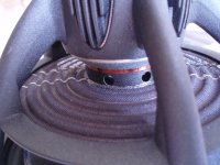
Interesting. That would indeed cancel vibration and distortion. It would appear the woofers pump air in and out of those chambers, similar to the functioning of an AMT. Would that be a correct visualization?The Orion 4 configuration is the same setup as the Phoenix woofers but with the enclosure rotated 90 degrees. The only possible issue here would be cone sag, but I'm sure he's investigated and is comfortable with the Seas drivers in this respect.
Dipole Woofer
Cheers,
Dave.
Dipole Woofer
Cheers,
Dave.
If you stack the two Aurasound and the SEAS / SS drivers one on top of the other, the center of the SS10 will be at least 125 cm (50") above the ground. Is that really what you want?
Employing the NS15 in pairs just to get reduced distortion, and as MIDwoofers only, doesn`t look like a rational design decision to me. One alone should move more than sufficient air in this application with ease.
Rudolf
Employing the NS15 in pairs just to get reduced distortion, and as MIDwoofers only, doesn`t look like a rational design decision to me. One alone should move more than sufficient air in this application with ease.
Rudolf
If you stack the two Aurasound and the SEAS / SS drivers one on top of the other, the center of the SS10 will be at least 125 cm (50") above the ground. Is that really what you want?
Employing the NS15 in pairs just to get reduced distortion, and as MIDwoofers only, doesn`t look like a rational design decision to me. One alone should move more than sufficient air in this application with ease.
Rudolf
The NS15s will not just be midwoofers. They will be highpassed at 40Hz and augmented below by bass-reflex woofers. The displacement requirements for 120dB at 40Hz with a 400mm baffle are non-trivial.
I never noticed that the Neo10 drivers were commercially available. They look especially interesting.
[snip] But you can get different response if the front and back volumes of the housing are as different as in a W frame a la Linkwitz. I would prefer a symmetrical position of the drivers ..[snip]
Rudolf
Yes, but the significance of this asymmetry will depend the design of the cavities. Even if the cavity resonances are different, they are probable high enough above the woofer cut off to have little effect. Even the Orion H frame had different front and rear resonance, though neither was particularly significant.
I'd like to incorporate them into a linear phase multi-way system. A Duelund XO with a=2 could be nice. If the interdriver spacing is minized, a=sqrt(3) could be very interesting.
Dueland crossover are not linear phase, and at best, the Dueland transfer functions are, at best, just acoustic targets.
Yes, but the significance of this asymmetry will depend the design of the cavities. Even if the cavity resonances are different, they are probable high enough above the woofer cut off to have little effect. Even the Orion H frame had different front and rear resonance, though neither was particularly significant.
john k,
Is there anyway to estimate the resonance? As far as I understand, the fundamental mode is a function of mass. If we knew the driver displacement and the geometry of the cavity, could we estimate the resonance or are there simply too many elements involved?
Your Nao Note loudspeakers look fantastic and the measurements look equally great. How did you optimize the midrange waveguide (ie torus)? Was it based upon a geometric relationship or did you consider the velocity distribution contributed by the SS 10F?
Also, since your loudspeaker arrangement is asymmetrical, wouldn't the acoustic center be a function of frequency? Specifically, wouldn't it move from the top of the loudspeaker to the center of your woofers? Is this effect audible?
Thanks,
Thadman
Also,
Consider this...
The Neo10 loudspeaker topology may be ideal for this application. However, its height is a bit of a problem. We want the loudspeaker to generate spherical wavefronts. The wavefront from a linesource expands in 2 dimensions in the nearfield. This is why it experiences an attenuation of -3dB per doubling of distance instead of -6dB and is why it can never have an ideal impulse response.
An acoustic solution may provide an answer to our problem. If we arranged two Neo10s around a single Neo3 and placed foam wedges that tapered in thickness (varies in vertical) towards the center, we might be able to achieve our goal of constant directivity in the vertical domain. Since the arrangement is symmetrical, the acoustic center shouldn't be a function of frequency.
If you're having trouble visualizing this, take a look at the RAAL 140-15D.
http://www.stonessoundstudio.com.au/stone/Raal/140-15d-a.jpg
Any thoughts?
With regards to distortion reduction, would it be optimal to align the voice coils or the front of the drivers? I have seen both used.
Also, in order to assume cancellation of harmonics, wouldn't the acoustic centers have to be spaced less than 1/4 wavelength of the highest desired harmonic?
For example, to cancel the 3rd harmonic of 150Hz, wouldn't the acoustic centers have to be (150*3*4=1800Hz, 340290/1800=190) spaced <190mm or <7.5"?
From a physics standpoint, what matters for cancellation is the path length difference between the two drivers to the listening position and the usual 1/10 wavelength rule of thumb for smallness applies---it's common to use looser rules in audio but also often not so accurate. I would, however, expect the ~2ms threshold for different sounds to be heard as one applies. So psychoacoustics may permit looser tolerances than the physics would suggest.
It's a somewhat time consuming but straightforward experiment to vary the spacing of push/pull drivers in a nude swinging dipole and take measurements. But, once that's done, there's data to design from instead of speculation.
It's a somewhat time consuming but straightforward experiment to vary the spacing of push/pull drivers in a nude swinging dipole and take measurements. But, once that's done, there's data to design from instead of speculation.
First trouble is: The acoustic center moves with frequency.
Second trouble: Non-symmetric drivers (cone and basket) have different acoustic centers, if looked from front or rear.
My latest measurements suggest that you better (start to) align along the front of such drivers than along the voice coils.
But, as twest 820 already mentioned, the truth is only found in actual measurements.
Rudolf
I've found the acoustic center's pretty stable and that aligning to the average depth of the cone and dustcap is a good starting point---that's often right around forward end of the basket's openings. Seems like the additional path length around the spider and magnet more or less cancels the cone being further back than the dust cap for the rear wave. I'd expect these approximations to break down as the driver becomes acoustically large. But I've never needed to operate a woofer much above it's dipole peak so I haven't looked.
- Status
- This old topic is closed. If you want to reopen this topic, contact a moderator using the "Report Post" button.
- Home
- Loudspeakers
- Multi-Way
- Push Pull Dipole