Please bear in mind that when I built the System IVs, there was very little reliable theory on TL speakers. That's why I built the variable prototypes to test the bass response. I took the speakers up to John Collinson (ex Wharfedale and Castle Acoustics) for measurement but making nearfield measurements wasn't so easy, particularly as there were four drivers and the line exit was designed to be as far as possible from the drivers.BAM said:7V Steve: So, to get the required enclosure volume, I should model a ported enclosure, with a port that tunes the enclosure to a certain frequency, but instead of the reflex port I should substitute the line, correct? And perhaps the line should be the length of a quarter of the wavelength of what would otherwise be the enclosure's tuning frequency. Also correct?
Unfortunately, I can't lay my hands on the resulting measurements at the moment so I'll rely on my memory. Of course the Bandor units that I used at that time are not the units available today.
The first thing to say is that, as I played with the prototype, varying the box size and opening & closing the port (switching the line on or off) it became clear that I wasn't modelling the system on a ported enclosure but rather a sealed box.
There was definitely deeper and 'more' bass with the line open but it was difficult to determine accurately as opening the line also resulted in a significant reduction in the 2nd harmonic distortion so the bass sounded deeper anyway. In any case, there was plenty of scope for tuning the line by varying the amount and positioning of the stuffing (long-haired wool).
The line cross section was very slightly under the combined cone area and the port in the cabinet had the same area as the line.
I chose a relatively large box size to get the overall (sealed box)Q down to about 0.6. This was because the speaker was designed to work alone without any bass or subs and I preferred the sound like this. The cost was greater cone excursion. My new speakers, designed for use with bass speaker(s) are in a smaller enclosure with the Q nearer to 0.7.
The line was, as you correctly surmise, a quarter wavelength design. Again I could vary the length of the line (by opening different ports at the line end). Subjectively, a shorter line didn't seem to work as well, although in the end I did choose a compromise based partly on the aesthetics of the thing (I'm so ashamed)

As I said, I don't entirely believe the theory put forward by the original Daline designer although I had owned two pairs of his original designs and was very fond of them. However, when I played with my prototypes I found that closing the port opening to the line by up to about 50% made no material difference. This made me sceptical that there was a normal ported box principle at work here. Nevertheless, the port and line definitely behaved as a low pass filter just as you would expect from any line. I couldn't detect any difference whatsoever in the mid-range with the port (and line) open or closed.
So BAM, I would build a box size based on the Qts that you would choose for a sealed box and then add a quarter wavelength line and tune with the line stuffing.
There you have it. Sorry I'm a bit vague but come back if you have any more questions and I'll try to dig deeper to see if I can find the measurements taken at the time or remember any more. I'm also going to visit a friend who has a pair of operational System IVs and he has some photos of the variable prototypes. I'll see if I can borrow them and post them here. Should give everyone a laugh.
I must say, this has been an intensely mind-expanding experience for me, and I appreciate the opportunity to rack the brains of professionals in this which is my first foray into the area of transmission line loading.
Here's the extent of my understanding of Daline theory:
1. Model a sealed box with the appropriate Qtc for the desired response.
2. Add a quarter-wavelength transmission line, using traditional quarter-wavelength transmission-line theory to determine the area of the line. The opening into the box should be no less than 50% of the line area.
But there's a problem.
In modeling my NSBs in a sealed box of 33 liters, I get a Qtc of about 0.8, which means boom, boom, boom. The dimensions of the upper enclosure for this simulation are 16" high, 18" deep, and 7 inches wide (yielding 2016 cu. in., or 33 liters.) This does not look good for Homestar Runner. Should I worry about the Qtc of the system if my goal is to get lots of bass from this? Or will adding stuffing to the line tighten things up?
BAM:
Have you checked the specs for the NSB's you are talking about? I postem them in post #15, here's the link:
http://www.diyaudio.com/forums/showthread.php?postid=205207#post205207
The Vas of the woofer is not 0.8 cu ft. It is 0.08 cu ft, or 20% less than 0.1 cu ft. The Vas of the two NSB's is 276 cu in. so the box you modeled is over 7 times larger than the speakers' Vas. You can make the box much smaller and still have the same numbers-the Qts won't go up much even if you make the box 17 liters instead of 33.
I am going to analyze the Focal Daline to see how that works. Be back later tonight or tomorrow.
BAM:
The reason is that the Vas is so small, that the Qts is not going to change in any reasonable size box. When the volume of the box gets to be 3 or 4 times the Vas of the speaker, the speaker is essentially working in free air, except for the back wave being cut off.
Qtc = square root of: [(Vas/Vb) + 1] times Qts.
You have to really be twice Vas or less for the Qtc to change.
Not with a Qts of 0.79. Earlier in this thread you said it was a Qts of 0.35 or something. Please check that-Parts Express says the Qts. is 0.79, which is certainly not fit for a ported box.
EDIT: Oops. I see you mentioned that you already did re check the figures in WinISD. Sorry.
The reason is that the Vas is so small, that the Qts is not going to change in any reasonable size box. When the volume of the box gets to be 3 or 4 times the Vas of the speaker, the speaker is essentially working in free air, except for the back wave being cut off.
Qtc = square root of: [(Vas/Vb) + 1] times Qts.
You have to really be twice Vas or less for the Qtc to change.
WinISD says that this driver's EBP best suits it for a vented box.
Not with a Qts of 0.79. Earlier in this thread you said it was a Qts of 0.35 or something. Please check that-Parts Express says the Qts. is 0.79, which is certainly not fit for a ported box.
EDIT: Oops. I see you mentioned that you already did re check the figures in WinISD. Sorry.
BAM said:Here's the extent of my understanding of Daline theory:
1. Model a sealed box with the appropriate Qtc for the desired response.
2. Add a quarter-wavelength transmission line, using traditional quarter-wavelength transmission-line theory to determine the area of the line. The opening into the box should be no less than 50% of the line area.
Originally posted by kelticwizard
I am going to analyze the Focal Daline to see how that works. Be back later tonight or tomorrow.
Yes, BAM that's my experience of the design process of the Seventh Veil - System IV, although I'd be cautious of the opening being 50% of the line area when using other drivers. I would say, that as a general rule the box opening should be approximately the same as the line cross sectional area.
I've just dug out and reread (briefly) the two original articles by the Daline designer Robert Fris (Hi-Fi News & Record Review - November 1974 and May 1975). As I said, my own findings didn't concur with everything that is said about the Daline system. The major differences between Daline and System IV were:
1. The cavity volume of the Daline appears to be less than that of the 'sealed box' model used with the System IV.
With the drivers that I used in my variable prototype I found that the bass response improved as I increased the size of the cavity/box.
2. A tapered 1/4 wave pipe was used in the Daline. I found that the taper made no material difference so I used a rectangular section steel pipe (no taper).
3. The Daline is claimed to be non-resonant or aperiodic from 20Hz upwards. I found that the System IV measured like a normal TL with the two resonant peaks that can be tempered by damping.
I did find, like Robert Fris, that less damping was needed in the line than is normally suggested for a conventional TL.
I hope that this shines more light on the subject.
Has anyone else built any Daline type speakers using different drive-units and/or dimensions than the original Robert Fris designs?
so I just read the description of these little 4" beasts. It says they would work in a line array. Any thoughts on this. I've always kind of been interested in these if nothing else, then for their visual effect. for 90 cents, can you really go wrong? Any thoughts on maybe a line of 16 drivers a piece. I wouldn't be looking for something that blew me away sound quality wise. Maybe just something that got pretty loud for all those raging college parties I'll be throwing next year ( I'm a senior in Electrical engineering HA!). Although of course I will do a search, does anybody know of a project that might be something like this?
@dunderchief: You could do it, but you would probably get a good deal of comb filtering. Being an EE major, though, you should know how to build an active EQ circuit to compensate for that. I understand that if you search the Parts Express message board for NSB, you should turn up all results relating to the NSBs, including several designs. One of these is a sealed enclosure. Please note, however, that the NSBs do not handle much power at all, only about 5 watts RMS. While this would be good for tube amp users, it probably wouldn't be quite so good for big, powerful solid state amplifiers.
Off topic, what college are you graduating from? This fall, I will be a freshman at Purdue University.
@kelticwizard
Above, I mentioned that I knew of a sealed enclosure project that uses the NSBs. Could I just take this sealed design and then add the line to the bottom and be done with it?
@7V
Subjectively, how would you describe the bass of the System IVs? Was it fairly deep with less control? Or was it very controlled but not quite as deep?
I would describe the bass of the System IVs as controlled and deep (low Q) but light. It's certainly tuneful- every note is clear - but, as I said, a little light.BAM said:@7V
Subjectively, how would you describe the bass of the System IVs? Was it fairly deep with less control? Or was it very controlled but not quite as deep?
Graduate, wow, I don't think that work is in my vocabulary at the moment. I spent a year in New Zealand, so even though I'll be a senior with credits, I'm just starting my junior year course work. Not to mention at the moment I'm declared as a double major in Computer and electrical engineering with minors in Computer science, math, physics, and musical performance, so I might need to drop at least one of those if I ever want to graduate. I'm at Oregon State University by the way.
BAM said:
@kelticwizard
Above, I mentioned that I knew of a sealed enclosure project that uses the NSBs. Could I just take this sealed design and then add the line to the bottom and be done with it?
Not if the Focal Daline kit 044 is any guide.
The Focal Daline kit 044 uses a very low Qts midbass: 0.2. If the top chamber was sealed from the Line, the Qtc of the system would be only about 0.3. There are two different Focal drivers used in the Daline kit-the 5N412 DBL and the 5NV4211 DB, and they both have pretty similar specs. So it is not a typo.
I have not seen a response curve for the Daline. However, Focal gives the -3 dB down point as 40 Hz, and Focal is a quality manufacturer.
The top chamber is 0.54 cu ft. The Line has three sections of 21.875", 21.75" and 20.5" for a total line length of 64". The width and depth of the line is 3.5" by 6". Normally, a line of this size and length would tune a 0.54 cu ft box to 39 Hz or so.
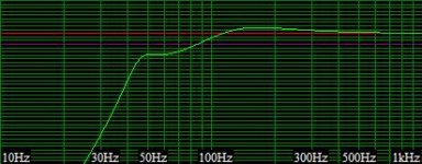
I modelled the Daline box as if it was purely a reflex box. Win ISD does not model Transmission Lines, so the Quarter Wave action of the port is not accounted for in this chart below.
What we see is a reflex box with a driver with a Qts that is far too low. The sloping dip shows that.
Attachments
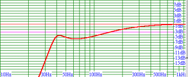
I can assure you , Focal would not put out a kit that gives a response that looks like that. So the quarter wave action of the port is an important factor here.
The quarter wave of a tube 64" long is the length of one wavelength, (13,500 in) divided by 64", and then divided by 4. This gives us 53 Hz. So the quarter wave action of the tube is 53 Hz.
As you can see, 53 Hz is located somewhere in the middle of that response dip. It must give the response a boost at that point, though we don't have the software to calculate it.
So if the Focal Daline is any guide, we have the following rules:
A) Start with a very low Qts woofer.
B) Put in a chamber to raise it's Qtc to 0.3 to 0.35.
C) Make a Line that tunes the Top Chamber to the Fs of the driver-not the Fc in the Chamber.
D) Make the length of the Line so that the quarter wave resonance tunes the Line to a frequency 1.4, (half an octave) above Fb.
Well, that is the way the Focal Daline kit 044 works, anyway.
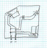
Here are the plans. There is a site with the plans in Metric, but those dimensions are imprecise and a little off. These drawings are clear. Metric types can convert inches to mm merely by multiplying by 25, so it is simple.
Oh, yes, you see the shaded pieces in the enclosure? That is not wood or MDF-that is just damping material. they call it Black Hole 5-I am not familiar with it. Apparently, this Daline is not stuffed with polyfill-just lined with heavy damping material.
http://216.239.37.104/translate_c?h...rch?q=daline&start=20&hl=en&lr=&ie=UTF-8&sa=N
And here is the drawing:
The quarter wave of a tube 64" long is the length of one wavelength, (13,500 in) divided by 64", and then divided by 4. This gives us 53 Hz. So the quarter wave action of the tube is 53 Hz.
As you can see, 53 Hz is located somewhere in the middle of that response dip. It must give the response a boost at that point, though we don't have the software to calculate it.
So if the Focal Daline is any guide, we have the following rules:
A) Start with a very low Qts woofer.
B) Put in a chamber to raise it's Qtc to 0.3 to 0.35.
C) Make a Line that tunes the Top Chamber to the Fs of the driver-not the Fc in the Chamber.
D) Make the length of the Line so that the quarter wave resonance tunes the Line to a frequency 1.4, (half an octave) above Fb.
Well, that is the way the Focal Daline kit 044 works, anyway.
Here are the plans. There is a site with the plans in Metric, but those dimensions are imprecise and a little off. These drawings are clear. Metric types can convert inches to mm merely by multiplying by 25, so it is simple.
Oh, yes, you see the shaded pieces in the enclosure? That is not wood or MDF-that is just damping material. they call it Black Hole 5-I am not familiar with it. Apparently, this Daline is not stuffed with polyfill-just lined with heavy damping material.
http://216.239.37.104/translate_c?h...rch?q=daline&start=20&hl=en&lr=&ie=UTF-8&sa=N
And here is the drawing:
Attachments
kelticwizard - how did you model the Focal Daline as if it was a reflex box - without a port? What does the closed box response look like?kelticwizard said:I modelled the Daline box as if it was purely a reflex box. Win ISD does not model Transmission Lines, so the Quarter Wave action of the port is not accounted for in this chart below.
What we see is a reflex box with a driver with a Qts that is far too low. The sloping dip shows that.
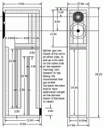
I have dug up some more information on the Seventh Veil System IV ...
Driver parameters - these come from the Bandor web site and will have been modified a little since System IV days but probably not significantly (4 off):
Fo: 65Hz
Qms: 1.67
Qes: 1.07
Qts: 0.60
Vas: 2.06 litres
Cms: 2.15mm/N
System IV box volume: 9 litres
System IV line length: 180cm (61")
keltic, looking again at the line configuration, I would say that the System IV line is probably a little shorter, say 174cm (68.5"). Previously it should have read 71" not 61"
I'd be very interested to see your modelling analysis and I will probably manage to dig up the original actual measurements.
I'd be very interested to see your modelling analysis and I will probably manage to dig up the original actual measurements.
7V said:
kelticwizard - how did you model the Focal Daline as if it was a reflex box - without a port? What does the closed box response look like?
The Daline makes use of two phenomena-the relationship between the volume of air in a box and the port that is put there. This is a simple bass reflex. This, Win ISD, free version, models.
The Daline also makes use of another phenomenon: The pipe resonance of an extra long port. This, WinISD, free version, does not model.
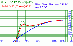
So I calculated the volume of the top chamber-it was 0.54 ft³.
I calculated the height, width and length of the port, or Line: it was 3.5" x 6" x 64".
So I modelled the Focal 412DBL, the speaker that is in the Focal Daline Kit 044, and put in 0.54 ft³ for box volume, 3.5" x 6" for port dimensions, and kept changing the desired Hz value until I hit 64" length. That desired Hz value was 40 Hz. (Normally, WinISD takes the box volume, port area, and desired Fb and tells you how long the tube must be).
Since WinISD has no provision to measure pipe resonances, I knew that the curve produced would look different from the actual output. It is therefore useful for predicting how important Line output is in this enclsosure. As you can see, the Daline, as least as practiced by Focal, most certainly is not just a fancy name for a simple reflex box. The pipe resonance action must be substantial, for Focal would never sell a kit with a response curve so bad.
The volume of the speaker chamber, (top chamber), is 0.54 Ft³. The length of the Line is 3.5" x 6" x 64". The volume of the Line, which I decided to calculate, is 0.7777 Ft³.
Focal claims an F3 down point for the kit 044 of F3=40 Hz.
Just for the heck of it, I decided to model four curves. The reflex with the top chamber volume, (o.54 Ft³), tuned to 40 Hz. Port was negligible in size. That curve is in red.
The reflex with a box volume of both top chamber and Line together, (1.3Ft³). Fb=40 Hz. Port was negligible in size. That is the green curve.
I found that the closed box curve for both the chamber volume, (0.54Ft³), and total internal volume, (1.3Ft³) were identical. So I just ran one curve in blue for both.
These will give you an idea of just how much the pipe organ resonances help and how the Daline stacks up against the ported and reflex box in the "F3 per cubic inch" sweepstakes. It turns out that it stacks up quite well, assuming the Line output due to Quarter wave output smooths out that curve.
If there are any more questions, please let me know.
Attachments
7V said:
Driver parameters - these come from the Bandor web site and will have been modified a little since System IV days but probably not significantly (4 off):
Fo: 65Hz
Qms: 1.67
Qes: 1.07
Qts: 0.60
Vas: 2.06 litres
Cms: 2.15mm/N
System IV box volume: 9 litres
System IV line length: 180cm (61")
A) 9 liter box volume-is that for just the top chamber or did you count the volume of the line itself?
B) System IV Line length-68 in. Can you give us the height and width of the line, (or area), in addition to Line length?
9 litres is just the top chamber.kelticwizard said:
A) 9 liter box volume-is that for just the top chamber or did you count the volume of the line itself?
B) System IV Line length-68 in. Can you give us the height and width of the line, (or area), in addition to Line length?
Line is approximately 5" x 2" rectangular (no taper).
- Status
- This old topic is closed. If you want to reopen this topic, contact a moderator using the "Report Post" button.
- Home
- Loudspeakers
- Multi-Way
- Just for the sake of asking... (about Bass)