I am trying to setup my DIY measurement system with WM-61A modded capsule and Linkwitz's mic amp. I built it sometime ago but gave up due to Speaker Workshop complexity.
I have now installed Arta and trying to get this up and running again. I have SB Live! lying somewhere, and for now have set it up using built in Realtek sound card.
I tested the mic by simply recording my voice and playing it back, and it sounds ok to me. Then I tried frequency response test (FR1) with quite low level pink noise played from GC to Hatt-MKIII and this is what I got.
I could not play pink noise loud in the middle of night, but I even don't know how loud should I play, where to place the mic, what should I expect as result, if mic and amp are working OK, etc. In short, too many unknowns in one equation") How this graph looks to more experienced diyers?
How this graph looks to more experienced diyers?
I have now installed Arta and trying to get this up and running again. I have SB Live! lying somewhere, and for now have set it up using built in Realtek sound card.
I tested the mic by simply recording my voice and playing it back, and it sounds ok to me. Then I tried frequency response test (FR1) with quite low level pink noise played from GC to Hatt-MKIII and this is what I got.
I could not play pink noise loud in the middle of night, but I even don't know how loud should I play, where to place the mic, what should I expect as result, if mic and amp are working OK, etc. In short, too many unknowns in one equation
How this graph looks to more experienced diyers?Attachments
Hi Zdr, it would probably help to know how the measurement was done, Without knowing this it is difficult to comment.
I'm not familiar with ARTA, but the fist thing that strikes me is that it doesn't look like a typical gated measurement, or perhaps it is but the gating has been set to include some reflections, hence the "fuzzy" look at the higher frequencies.
It looks too clean to be a raw in room measurement, but it does look like it includes room interations.
Certainly I would say for a first try you are on the right track.
As a starter I would suggest placing the speaker in the middle of the room (removing any hard furniture if you can. try and get it 1/2 way between the flloor and the ceiling and as far from any other objects as possible. put your mic on axis one meter away.
As far as levels go, one way to set it is to put your multimeter (on AC) on the output of the amp when you are playing the signal, Set the levels to get 2.8V and you will probably be ok (remove the multimeter after setting the levels as It can effect the results). Wear hearing protection too!! I was surprised just how loud 2.8V is!!
Even though it is a different program, you could check out the Holm Impulse threads here as well as there are plenty of tips about doing measurements in them.
Tony.
Arta is fuzzy because you're not measuring with it correctly.
You need to switch it into impulse mode and make a measurement using an MLS signal.
If you do that you will end up with an
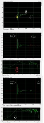
impulse response on the screen and looks like the first graph in the attached image.
Notice the arrows.
The yellow one shows the start of the impulse response.
The white one shows the end of the impulse response.
The grey arrow shows the first serious reflection from something and is likely to be the closest hard reflective surface between the mic and the loudspeaker.
Arta allows to you to gate the measurement and let in, or keep out, as much influence (reflections) from the room as you want.
Left click allows you to set the start point, on the second graph, this is the first grey arrow, and as you can see it's set at the start of the impulse.
The end point you place with right click. I decided to use the right hand grey arrow as my end point.
The corresponding frequency response is displayed below.
Note that the FR is still slightly fuzzy, this is because I have a sub optimal setup for measuring as there are hard reflective surfaces all around the measuring area.
Now note the position of the red arrow. Below it is a green line that goes just beyond 300hz. This is showing that due to the short gate length we can only get accurate data to around 300hz.
Now lets try extending the gate end point to include the first reflection.
As you will notice in the last graph the frequency response is a lot fuzzier, this is because we've included the reflection. Also note at the white arrow the same green line has now moved down closer towards 200hz.
As the gate length increases so does the low frequency boundary, but is it accurate? No of course not, it's including the reflection and you don't know if the bumps in the response are a reflection or really produced by the loudspeakers.
To remove reflections you can perform what's known as a near-field response. To do this you place the microphone next to the loudspeaker cone and measure, make sure nothing is clipping though!
This will create a much cleaner impulse response and allow you to set the gate much longer. This gives you very accurate measurements but doesn't take into consideration baffle effects, such as diffraction. These are useful for making low frequency measurements.
To make measurements that include how the baffle affects the sound you have to perform a far field response. As we have seen though, these have limited low frequency accuracy. The common thing to do is make both far and near field measurements and splice the near-fields accurate low frequency onto the far-fields high frequency response. You will need to most like add in the simulated effect of baffle step.
You need to switch it into impulse mode and make a measurement using an MLS signal.
If you do that you will end up with an
impulse response on the screen and looks like the first graph in the attached image.
Notice the arrows.
The yellow one shows the start of the impulse response.
The white one shows the end of the impulse response.
The grey arrow shows the first serious reflection from something and is likely to be the closest hard reflective surface between the mic and the loudspeaker.
Arta allows to you to gate the measurement and let in, or keep out, as much influence (reflections) from the room as you want.
Left click allows you to set the start point, on the second graph, this is the first grey arrow, and as you can see it's set at the start of the impulse.
The end point you place with right click. I decided to use the right hand grey arrow as my end point.
The corresponding frequency response is displayed below.
Note that the FR is still slightly fuzzy, this is because I have a sub optimal setup for measuring as there are hard reflective surfaces all around the measuring area.
Now note the position of the red arrow. Below it is a green line that goes just beyond 300hz. This is showing that due to the short gate length we can only get accurate data to around 300hz.
Now lets try extending the gate end point to include the first reflection.
As you will notice in the last graph the frequency response is a lot fuzzier, this is because we've included the reflection. Also note at the white arrow the same green line has now moved down closer towards 200hz.
As the gate length increases so does the low frequency boundary, but is it accurate? No of course not, it's including the reflection and you don't know if the bumps in the response are a reflection or really produced by the loudspeakers.
To remove reflections you can perform what's known as a near-field response. To do this you place the microphone next to the loudspeaker cone and measure, make sure nothing is clipping though!
This will create a much cleaner impulse response and allow you to set the gate much longer. This gives you very accurate measurements but doesn't take into consideration baffle effects, such as diffraction. These are useful for making low frequency measurements.
To make measurements that include how the baffle affects the sound you have to perform a far field response. As we have seen though, these have limited low frequency accuracy. The common thing to do is make both far and near field measurements and splice the near-fields accurate low frequency onto the far-fields high frequency response. You will need to most like add in the simulated effect of baffle step.
Attachments
Hi ZDR,
The flat to 20 Hz is a side effect of the gating. The gating in that measurement means that frequencies below about 1.3Khz should be ignored, as they have no resemblance to reality. If you move the gating out to just before that 60cm blip you should get a bit more low freqency resolution. The Gating indicator should move lower in freq which will show you where the new cutoff point (below which the fr data is suspect).
Tony.
The flat to 20 Hz is a side effect of the gating. The gating in that measurement means that frequencies below about 1.3Khz should be ignored, as they have no resemblance to reality
. If you move the gating out to just before that 60cm blip you should get a bit more low freqency resolution. The Gating indicator should move lower in freq which will show you where the new cutoff point (below which the fr data is suspect). Tony.
good cheap sound card?
Is there a cheap good sound card that works well with Arta or any other measurement sw out there? I tested my built in AC97 which comes out with very low THD but high noise from mobo, resulting in too high THD+N = 0.18%. SB Audigy I had lying around produced some ridiculously high figures for THD alone, and old SB live threw my Windows 7 into BSOD.
So here I am, looking for good alternatives.
0.18% THD is pretty low. What are you trying to measure? If just frequency response, take a measurement without the speaker hooked up. Then take a measurement of the speaker. Over lay the two curves. This will let you see if the noise floor is causing a problem with the measurement.
If you're trying to measure speaker distortion, I would not worry about it until it gets up to around 10% or higher. So if your noise floor is at 0.18%, that gives you room to work with.
If you're trying to measure speaker distortion, I would not worry about it until it gets up to around 10% or higher. So if your noise floor is at 0.18%, that gives you room to work with.
Is there a cheap good sound card that works well with Arta or any other measurement sw out there? I tested my built in AC97 which comes out with very low THD but high noise from mobo, resulting in too high THD+N = 0.18%. SB Audigy I had lying around produced some ridiculously high figures for THD alone, and old SB live threw my Windows 7 into BSOD.
So here I am, looking for good alternatives.
Never mind, it seems that Audigy works cleanly only with 48KHz sampling rate. Only then THD+N drops below 0.01, so I am good to go.
When measuring with HOLMImpulse I found I have to show a "raw measurement", which disabled the gating, to get useful data below the gating frequency. I then apply whatever smoothing I want (1/6th octave is nice). The implication is a measurement which will be strongly affected by the room (I was measuring a desktop speaker in nearfield, so that was ok, but otherwise you'll want to be outdoors I guess).
How were you testing the sound cards thd? RMAA? My Audigy II ZS is excellent. BUT it needs the levels set right to be so... recording level set to 50% from memory (which I think is 0db) and the output level also set to no more than 85% (depending on what gives high enough levels for RMAA to work.
I use my audigy II with 96Khz recording and 192Khz playback from memory though this has been on XP with probably quite old drivers...
Tony.
I use my audigy II with 96Khz recording and 192Khz playback from memory
though this has been on XP with probably quite old drivers... Tony.
- Status
- This old topic is closed. If you want to reopen this topic, contact a moderator using the "Report Post" button.
- Home
- Loudspeakers
- Multi-Way
- Speaker measurement with WM-61A