I compared an Altec 416-8C Onken (n = 5.7) with vent area (Av) = driver effective area (Sd) to a comparable MLTL and while the Onken was a lively performer, the MLTL with its single smaller, shorter vent sounded just as open/dynamic, yet smooth as a baby's bottom with a better perceived transient response.
Consequently, the Onken's owner copied my MLTL design except added fake Onken vents because he liked the look so much, but the single 8" diameter vent was actually in the back. Internally, it was folded in half to form an inverted 'U' get the TL's high aspect ratio.
GM
Could you explain the advantages of the MLTL GM
Otherwise I have to ask some one named Greg Monfort
") .
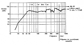
.You need look no further than the peaking Fb and lumpy measured response above it in the French magazine's article.
This is the only one I've found. It's from 1977. Is that the one you mean, or have you seen another?
Attachments
Onken = QB4 with Vent of 85 to 100 percent surface area as Sd
I suppose there is no distortion caused by the big vent it shout reduce distortion IMO.
It's my understanding that Onken specified a Av = Sd and that later generations 'relaxed' this down to 75% over time.
It maximizes vent efficiency, so is a form of lowering distortion until it causes the system response to become under-damped, but there's no 'free lunch' here since the vent's output rolls off as a function of its Q, so depending on the alignment it can have enough out of phase output to audibly comb filter with the driver's front radiation: Essay
Also, vents are 1/2 WL resonators, so have both even and odd pipe harmonics and since these are independent of an XO's effect on limiting useful BW output, we don't want them 'singing along' increasingly out of phase with the driver with increasing frequency until they decay below audibility on their own.
From this we see that for high SQ (as opposed to what one may consider most pleasing to the ear
), such large vents need to be critically damped; with the most common way being either blanking off one or more of them and/or stuffing them same as the mini-TLs they are to make them semi-aperiodic with the trade-off being an audibly reduced vent output.GM
Could you explain the advantages of the MLTL GM
Otherwise I have to ask some one named Greg Monfort
The 'long and the short of it'
is that you trade increased cab length and usually net bulk for increased vent efficiency without increased length, i.e. a lower distortion vent due to greater cab damping via 1/4 WL pipe loading: Quarter Wavelength Loudspeaker DesignGM
This is the only one I've found. It's from 1977. Is that the one you mean, or have you seen another?
That's the one and it's much better looking than some I've seen designed for other drivers. IIRC, Bill Woods (RCA fan) posted some along time ago on the HE forum. Not having the kind of measuring capability ya'll take for granted these days and no known/imagined need at the time to record for posterity anything I did beyond converting as much of my collected knowledge base into Lotus 1-2-3 spreadsheets as practical/possible, I can only 'prove' my assertions through the efforts of others.
GM
A bit weak excuse. You're using a computer it will have a 16bit sound-cart, that high resolution DA converter is a precision measuring instrument special for audio applications.Not having the kind of measuring capability ya'll take for granted these days
GM
freeware arta download. Mls software to measure both amplifiers or loudspeakers.ARTA Download
Only thing you need to buy is a behringer EMC8000 and a phantomsupply preamp. It is likely that a external(24bit) sound card with phantom supply input is a better option.http://www.amazon.com/Creative-Professional-0404-USB-2-0/dp/B000IXNE3E
And it is possible to measure THD as you like.
An externally hosted image should be here but it was not working when we last tested it.
Last edited:
I thought we were talking MLTL. I thought of a TL with a BR tube load at the end.The 'long and the short of it'
GM
For what I now read it is a TL with a Av = Sd a BR tube of 1/4 WL.
I thought we were talking MLTL. I thought of a TL with a BR tube load at the end.
For what I now read it is a TL with a Av = Sd a BR tube of 1/4 WL.
Ok I read about it it is a TL without open end only it is loaded so it isn't open nor closed. But loaded with BR tube
A bit weak excuse. You're using a computer it will have a 16bit sound-cart, that high resolution DA converter is a precision measuring instrument special for audio applications.
Oh really?! My peak DIY speaker building years ended back in the mid '70s and came to a screeching halt on 8-11-89, long before any inexpensive PCs, much less PC based measurement tools, were available. An immensely strong 'excuse' to my way of thinking.
Since joining net based audio forums, I've had zero real need to measure any speakers simply because I have only DIYed a few 'FR' driver MLTLs and none sounded 'off' far enough to require it beyond what my now burned out early '80s 1/3 octave RTA indicated to me.
So, with that in mind, what relatively inexpensive equipment was available to the DIYer back then that I wasn't aware of that was capable of measuring distortion or real time 'anything' beyond basic impedance, sine and square-wave plots? For sure none were PC based and unless I missed something in the instruction booklets, neither did any of my DIYed Heathkit testers.
GM
IIRC, Bill Woods (RCA fan) posted some along time ago on the HE forum.
Found a couple:
GM
Attachments
Found a couple:
GM
Andrea's onken
And the same 10cm nearfield measurement
The dips are port resonance about 270-540-910Hz I estimate.
Last edited:
Cool, thanks for the graphs! In Bill's graphs only the V-Vent looks really good.
Maybe we can get someone to do a distortion plot with HOLM or ARTA/Steps. Some single tone FFTs would be nice, too.
Onken W? Nothing special that I ever saw - except those funny little vents of different sizes.
.
Maybe we can get someone to do a distortion plot with HOLM or ARTA/Steps. Some single tone FFTs would be nice, too.
Onken W? Nothing special that I ever saw - except those funny little vents of different sizes.
.
Cool, thanks for the graphs! In Bill's graphs only the V-Vent looks really good.
Maybe we can get someone to do a distortion plot with HOLM or ARTA/Steps. Some single tone FFTs would be nice, too.
Onken W? Nothing special that I ever saw - except those funny little vents of different sizes.
.
Hi Panomaniac,
Why do you not measure your own Onken?
I did read you have them your self ain't I am right. And they have very special sound to your ears.
This solves one issue what we see will bee what you like.
I am very curious about your results.
HL
Something like this.YouTube - ALTEC A5 TESTINGI don't have Onken cabs. Always wanted to build a pair, never did. I use the Altec 828 (A5) bass cabs.
Thanks for the article GM. I'll look it over.
|
Through your enthusiasm about the Onken sound I am posting here. I also found a nice 15"driver to do so.
I wanted to build a OB and you said that the Onken can sound better I am confused.
With the 15'' I found I can build a OB and also test it in a Onken due its nice specs.
I will strip the horn out of horn almighty and make a onken+ horn.
Or Make a OB with the titanium Visaton TI100 as mid and with two ribbons and two titanium dome tweeters I want to make dipole tweeters. Is 10year old stuff that I have spare.
So I play around buy some and re-use some.
Although my latests project is very successful measures very precise low distortion perfect phase. And with all that it sounds very cool not clinical at all nice round bass a to some level warm highs(super low thd).
So I will tune them now with different types of capacitors and cables to the max I can. And then make a OB or Onken to see I can improve on that latests project.
Horn almighty did some parts of music sound very special (3D) only the midrange of the back-loaded horn was to restless that irritated a bit. Maybe together with the Onken It will be a super combination.
Last edited:
Andrea's onken
....
This is very interesting. It's like a decomposition of bass wave movement
Take 40Hz, it needs about 2 meter or 6 msec. to reach the maximum amplitude (1/4 wavelength). This reflects the measurements at 2ms and 5ms, but what happened at 20ms? Room refections? Port-cone cancellation?
This is very interesting. It's like a decomposition of bass wave movement
Take 40Hz, it needs about 2 meter or 6 msec. to reach the maximum amplitude (1/4 wavelength). This reflects the measurements at 2ms and 5ms, but what happened at 20ms? Room reflection? Port-cone cancellation?
Andrea measured at 1.5mtr when i am right. so when you see 2-5-20msec it is easy to predict where reflections are coming from considering the wave length. placement driver to baffle and floor and br-port (phase) with onkenport at front baffle a bit dipole like.
2msec = 68cm 500hz
5msec = 172cm 200hz
20msec= 688cm 50hz
Last edited:
- Status
- This old topic is closed. If you want to reopen this topic, contact a moderator using the "Report Post" button.
- Home
- Loudspeakers
- Multi-Way
- onken Onken w or A7 or Valencia