I would love some help here... ")
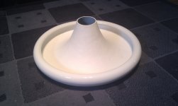
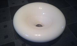
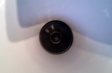
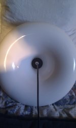
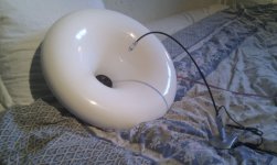
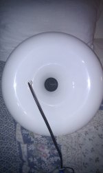
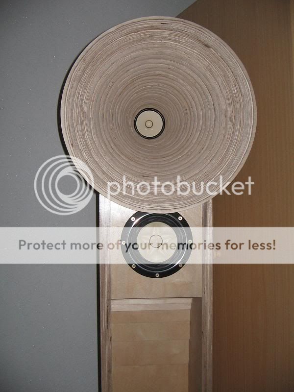
I'm working on my new speakers consisting of a pair of Scan-Speak 10F coupled to a pair of 48 cm JMLC horns pictured below.
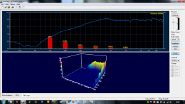
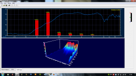
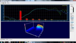
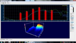
The drivers alone have a fairly flat response. But coupled to the horns they get, in addition to the horn boost, a huge wide bandwidth dip around 8,5 khz. See measurements below. Drivers simply laying in bed.
The drivers are fairly well coupled to the horns at the outer rim of the speaker surround. See pictures for this and mic position below.
Any ideas what might be the problem here?
I'm working on my new speakers consisting of a pair of Scan-Speak 10F coupled to a pair of 48 cm JMLC horns pictured below.
The drivers alone have a fairly flat response. But coupled to the horns they get, in addition to the horn boost, a huge wide bandwidth dip around 8,5 khz. See measurements below. Drivers simply laying in bed.
The drivers are fairly well coupled to the horns at the outer rim of the speaker surround. See pictures for this and mic position below.
Any ideas what might be the problem here?
Attachments
Lack of a phase plug?
Shouldnt need one when theres no compression ratio between horn throat and driver.
A meter would be too far for me as the room (about 12 sqm...) would affect the measurements too much. See the RT60 near and further away below. But I made some close and further away measurements on and off axis (dont know how many degree, but see the picture below), and this is the result...
How should I interpret this?
How should I interpret this?
Attachments
Last edited:
A meter would be too far for me as the room (about 12 sqm...) would affect the measurements too much. See the RT60 near and further away below. But I made some close and further away measurements on and off axis (dont know how many degree, but see the picture below), and this is the result...
How should I interpret this?
My guess
:Basically you are seeing the effects (or "non" effects) of freq. bounding to the waveguide.
As you move off-axis, you get closer to the waveguide and the signal "bounds" to the waveguide and gets a "lift" in pressure. Unfortunately the 0 degree axis is the the point of operation where there is the least "support" or bounding to the waveguide.
At 8 kHz the wavelength is just 1.7 inches long, at 10 kHz it's 1.35 inches long.
Now the "lift" in pressure on the 0 degree axis from 9 kHz could be in part due to the driver having some increase in pressure in this range on-axis, but probably has more to due with some additional resonance or "grouped reflection" of the driver in combination with the waveguide. Don't know. Obviously the loss in pressure off-axis in this freq. range has less bounding "support" AND is lower because of the driver itself (which has a greater natural loss in pressure off-axis at its highest operating freq.s).
BTW, what compelled you to use a standard extended range driver in a horn?
Yeah, the waveguide is beautiful, and we know the driver is very good!
Last edited:
At 8 kHz the wavelength is just 1.7 inches long, at 10 kHz it's 1.35 inches long.
The throat is 7,5 cm in diameter, which equals a wavelength of 4,6 khz, so I guess the horn/waveguide no longer provide any boost for the driver above this point?
The measurements dont quite show this tendency, but I guess thats due to the comprimised testing limitations. The dip is present at any distance in my room though, so this is most certainly defenitive anyways.
Now the "lift" in pressure on the 0 degree axis from 9 kHz could be in part due to the driver having some increase in pressure in this range on-axis, but probably has more to due with some additional resonance or "grouped reflection" of the driver in combination with the waveguide.
This could very well be. I will try to place some small diffusors inside the horn, and see what happens. Allthough one would think the horns expansion rate is too rapid for issues like these to occour. This doesnt seem to be a issue with other horns using wide range cone drivers, like Ferguson Hill and others.
BTW, what compelled you to use a standard extended range driver in a horn?
Yeah, the waveguide is beautiful, and we know the driver is very good!
I like the dynamics of horns
Compression driver dont work well as low as 500 hz without having an oversized and deep horn. Also smaller throats and longer horns beams more, and large diaphragm compression drivers requires a tweeter. AND I have yet to hear a metal diaphragm compression driver sound good. Thats why I went for a cone driver instead
The horn/waveguide is made by jzagaja.
The throat is 7,5 cm in diameter, which equals a wavelength of 4,6 khz, so I guess the horn/waveguide no longer provide any boost for the driver above this point?
The horn/waveguide is made by jzagaja.
Well clearly there isn't much loss in output up to almost 8 kHz. I'd look to the bounding surface and "trace-back" from there and reduce that freq. by a bit for various losses.
BTW, a "dip" is present in many designs on-axis, including the Gedlee products (..though of course the dip is marginal in those products by comparison.)
In your case I'd just put a low-pass on it around 6.5 kHz.. and a *very* steep one at that (elliptical/Cauer). Listen a bit off-axis and "blend" in a vertically directive super tweeter (above or below the horn) with a steep high-pass filter (..and I'd probably make that portion an active solution with an integrated "volume" control).
IIRC, Defo might wish to have this horn play all the way to the top.
And this horn (with 3in throat) may not have wide enough directivity to match the supertweeter @ 8kHz. I'm not sure the audibilty of this effect in real case, though.
I used to have a setup much worse than this, 7in throat mid horn and SUPERtweeter beyond 10k. Directivity was really awful (narrow sweet spot). Now this 3in throat at 8k maybe more than twice as good (or not so bad) than my previous 7in throat beyond 10k. However in a "picky" POV, another xover point is always a hard one to swallow for such a system with big round horn...
IIRC, Defo might wish to have this horn play all the way to the top.
And this horn (with 3in throat) may not have wide enough directivity to match the supertweeter @ 8kHz. I'm not sure the audibilty of this effect in real case, though.
I used to have a setup much worse than this, 7in throat mid horn and SUPERtweeter beyond 10k. Directivity was really awful (narrow sweet spot). Now this 3in throat at 8k maybe more than twice as good (or not so bad) than my previous 7in throat beyond 10k. However in a "picky" POV, another xover point is always a hard one to swallow for such a system with big round horn...
If you want it to play full-range in this config. then expect problems that can't be eq.ed.. (..and I personally wouldn't attempt a phase plug, because basically a large portion of the driver's excellent top-end performance is related to the dustcap.)
Again, think a little lower on the low-pass.
The issue of directivity (horizontally) for the super tweet is a good concern, but you can usually achieve similar patterns with a wide dispersion design (ribbon tweeter) that has an *absorption* waveguide. (i.e. various densities of foam.)
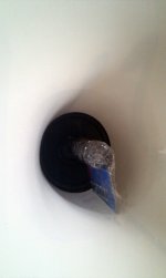
I tried a couple of very medicore "phase plug" sollutions today, and it seems they removed the dip to some degree. I got the best results from a small vacuum tube held in place by a piece of cardboard...
I guess a phase plug is the way to go then. Kudos to badman who suggested it in the first post... Don't really get it WHY it is needed though... The next challenge I guess would be to find a shape that works best. I guess the ripples in the top end will disapair with a more optimal and well done phase plug placement.
Any suggestions?
I guess a phase plug is the way to go then. Kudos to badman who suggested it in the first post...
Don't really get it WHY it is needed though... The next challenge I guess would be to find a shape that works best. I guess the ripples in the top end will disapair with a more optimal and well done phase plug placement.Any suggestions?
Attachments
Last edited:
I tried a couple of very medicore "phase plug" sollutions today, and it seems they removed the dip to some degree. I got the best results from a small vacuum tube held in place by a piece of cardboard...
I guess a phase plug is the way to go then. Kudos to badman who suggested it in the first post...
Any suggestions?
Ah, so you didn't puncture the dustcap for the plug. Good.
http://www.preference-audio.com/phaseplug.htm
Phase Plugs
Always best to take a measurement both on and off-axis to get an idea of what works well and what doesn't.
Last edited:
Ah, so you didn't puncture the dustcap for the plug. Good.
Hehe, no no
But I'm still curious about why the phase plug solves the problem. Normally to my knowledge, they are just used to extend freq response of drivers in horns and other applications.
That would help me a great deal with designing a proper phase plug...
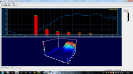
Made some new measurements now with different small objects as "phase plugs" including the vacuum tube mentoned earlier, and didnt quite get the same great results this time. I let the vacuum tube be held in place by a piece of foam in front of the driver instead of a piece of cardboard, and it didnt do the trick unlike the last time...
This is getting frustrating...
Many of the Ferguson Hill speakers (except the FH001) and others dont seem to need any fancy phase plugs and so on...

This is getting frustrating...
Many of the Ferguson Hill speakers (except the FH001) and others dont seem to need any fancy phase plugs and so on...
An externally hosted image should be here but it was not working when we last tested it.
Last edited:
Hehe, no no
But I'm still curious about why the phase plug solves the problem. Normally to my knowledge, they are just used to extend freq response of drivers in horns and other applications.
That would help me a great deal with designing a proper phase plug...
..that's why I provided the links.
Think of it as "pushing-out" higher freq.s to have a chance to become bound to the waveguide's walls.
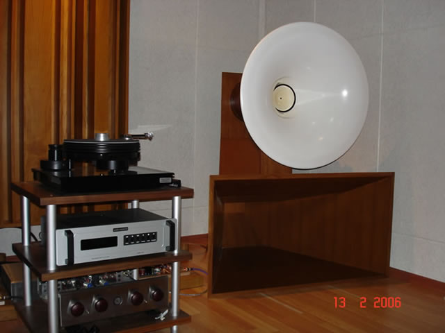
Other designs like the Ferguson Hill have the same problem, but not in the same pass-band.
That clear plexi horn has a fast expansion rate and probably does little to load the driver at freq.s below 2 kHz. Most of the output above 2 kHz then is from the driver (and not the bounded "gain" of horn + driver). Basically for a design like this to have some measure of linearity requires higher spl from the driver at freq.s above 2 kHz. Of course because it is a "fast expansion" there will less acoustic gain from the horn.
Your horn is more closely "coupled" (narrow) with a slow expansion by comparison so you have more gain. Essentially you are trading wider dispersion for spl gain that becomes more directive - like damming a river and just letting the water out a small hole (which radically increases the water pressure/flow-rate from that hole).
..that's why I provided the links.
Think of it as "pushing-out" higher freq.s to have a chance to become bound to the waveguide's walls.
I thought the purpuse of phase plugs in horns were to make the path lengths equal when a theres a compression ratio between driver and horn throat like in the pic below.
But it may be worth to try a plug like the one below about the size of the dustcap on the SS 10F. Without the compression chamber ofc.
Last edited:
- Status
- This old topic is closed. If you want to reopen this topic, contact a moderator using the "Report Post" button.
- Home
- Loudspeakers
- Multi-Way
- Scan-Speak 10F JMLC horn combo - large dip troubleshooting