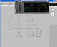
here are the snap shots of the screen
I don't think my tweeter model is 100% correct, but when I modeled your system the same spike was evident in the same place.
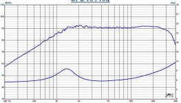
When I looked at the impedance graph it is evident the woofer has an impedance bump that is causing the issue.
Add a Zobel network to both the woofer and tweeter and the problem will go away.
The best response is when you use only one woofer with a Zobel and one tweeter. Using two woofers seems to be too much gain and you have a horrible impedance mismatch between the woofer and tweeter that confounds the response curves.
Last edited:
The spike is caused by the woofer's rising impedance at high frequencies.
To fix it, you need to connect a zobel network in parallel with the woofers.
1.5 ohms in series with 100uF should be about right.
That's nasty impedances you're working with, though. If I wanted to use two of those woofers in one box, I'd start by connecting them in series.
To fix it, you need to connect a zobel network in parallel with the woofers.
1.5 ohms in series with 100uF should be about right.
That's nasty impedances you're working with, though. If I wanted to use two of those woofers in one box, I'd start by connecting them in series.
The spike is caused by the woofer's rising impedance at high frequencies.
To fix it, you need to connect a zobel network in parallel with the woofers.
1.5 ohms in series with 100uF should be about right.
That's nasty impedances you're working with, though. If I wanted to use two of those woofers in one box, I'd start by connecting them in series.
Better yet, get two of these wired in parallel instead: Silver Flute 8Ω.
guys, can you please explain to me how the rising impedance can cause a 15db spike in the response when the spike present in the woofer is only 5db? Also how that spike shifts down in freq by 1Khz or more?
I would accept what you were saying if there was a 5db spike around the same place that the woofers response has that spike but the way I'm looking at the graphs, that is not what is going on here. that is the rising impedance would be making the crossover ineffective at those frequencies resulting in not enough cut, but either I'm reading the graphs incorrectly or there is something else going on")
good point about the two four ohms Loren, I didn't even notice that! The resistor to bring up the impedance will completely negate any spl benefit of running two in parallel, plus cause a whole lot of other issues. It would be better to run the two in series (no real gain in spl) or only use one, that to use two in parallel and a series resistor. The 8 ohm version is the best bet if the drivers haven't already been purchased.
edit: have you tried the one ohm resistor in series with the cap in the low pass yet mcmahon?
Tony.
I would accept what you were saying if there was a 5db spike around the same place that the woofers response has that spike but the way I'm looking at the graphs, that is not what is going on here. that is the rising impedance would be making the crossover ineffective at those frequencies resulting in not enough cut, but either I'm reading the graphs incorrectly or there is something else going on
good point about the two four ohms Loren, I didn't even notice that! The resistor to bring up the impedance will completely negate any spl benefit of running two in parallel, plus cause a whole lot of other issues. It would be better to run the two in series (no real gain in spl) or only use one, that to use two in parallel and a series resistor. The 8 ohm version is the best bet if the drivers haven't already been purchased.
edit: have you tried the one ohm resistor in series with the cap in the low pass yet mcmahon?
Tony.
It's an electrical resonance of the speaker's inductance and the crossover's capacitance. It's totally unrelated to the speaker's frequency response. The voltage across the woofer's terminals is actually boosted 15dB.guys, can you please explain to me how the rising impedance can cause a 15db spike in the response when the spike present in the woofer is only 5db?
The crossover is designed to operate at the ideal impedance of the load (woofer) and does not take into account changes in inductance (which causes the impedance bump) over the frequency spectrum.
All crossovers assume a perfect non-inductive resistance load. Obviously, in the real world this is not so with a woofer or any other driver.
When the impedance changes in the crossover circuit, so does the effect of that crossover and its slope. The effect can be pretty dynamic, too.
Lastly, X-Over Pro is a simple modeling program. There are many more variables in the real world that this program does not model or will not model well.
For that matter, any program that simply relies on T/S parameters to model a driver will not be able to bridge the gap between theory and reality very well (unless by happy accident).
The best mechanisms to model a driver involves real impedance data from the driver at various power levels and mechanical properties and dimensions of the motor of the driver. LEAP5 uses this approach and tests have demonstrated a very good model can be achieved in this fashion.
What that says about X-Over Pro (I have both programs, LEAP5 and X-Over Pro) is that X-Over pro only gets you part of the way toward the design. It will tell you if something is feasible, but to dial the design in you need to do actual testing followed by an iterative approach to get the best design.
This means that while the peak is seen in X-Over Pro it may not be there in the same point of the spectrum and with the same magnitude when you do a spectral sweep. X-Over Pro is just a simple tool and you still need to use the gray matter between your two ears.
guys, can you please explain to me how the rising impedance can cause a 15db spike in the response when the spike present in the woofer is only 5db? Also how that spike shifts down in freq by 1Khz or more?
I would accept what you were saying if there was a 5db spike around the same place that the woofers response has that spike but the way I'm looking at the graphs, that is not what is going on here. that is the rising impedance would be making the crossover ineffective at those frequencies resulting in not enough cut, but either I'm reading the graphs incorrectly or there is something else going on
good point about the two four ohms Loren, I didn't even notice that! The resistor to bring up the impedance will completely negate any spl benefit of running two in parallel, plus cause a whole lot of other issues. It would be better to run the two in series (no real gain in spl) or only use one, that to use two in parallel and a series resistor. The 8 ohm version is the best bet if the drivers haven't already been purchased.
edit: have you tried the one ohm resistor in series with the cap in the low pass yet mcmahon?
Tony.
Last edited:
Thanks Godfrey and Loren I see now where I was making an assumption, I was assuming that the freq response plot was based on an actual measured response, or at the very least a trace of each of the impedance and spl plots linked to. I did not realise that the entire driver was simulated!!
The post I made earlier (of my crossover) does have actual measured SPL and and impedance data and exhibits the same sort of thing. I haven't yet tried the crossover but I found that I have a 220uH coil so I think it might be time to try out the just the first stage of the low pass to see how it performs in real life. I'm not keen on making a zobel as the ones I experimented with didn't give good results.
Is what I suggested about putting a small resistance in series with the cap another valid way of dealing with the problem (rather than putting a zobel on the driver)? It certainly is a normal method in active circuits, and in my simulation seems to do the trick
Tony.
I see now where I was making an assumption, I was assuming that the freq response plot was based on an actual measured response, or at the very least a trace of each of the impedance and spl plots linked to. I did not realise that the entire driver was simulated!! The post I made earlier (of my crossover) does have actual measured SPL and and impedance data and exhibits the same sort of thing. I haven't yet tried the crossover but I found that I have a 220uH coil so I think it might be time to try out the just the first stage of the low pass to see how it performs in real life. I'm not keen on making a zobel as the ones I experimented with didn't give good results.
Is what I suggested about putting a small resistance in series with the cap another valid way of dealing with the problem (rather than putting a zobel on the driver)? It certainly is a normal method in active circuits, and in my simulation seems to do the trick
Tony.
Xpro impedance eQualization
I had the woofers equalization added to the schematic and the the model response drastically changed
Thanks for the help , I just started using this program, so from what I See it is a good starting point to put Woofer impedance equalization in from the start
I had the woofers equalization added to the schematic and the the model response drastically changed
Thanks for the help , I just started using this program, so from what I See it is a good starting point to put Woofer impedance equalization in from the start
Attachments
I had the woofers equalization added to the schematic and the the model response drastically changed
Thanks for the help , I just started using this program, so from what I See it is a good starting point to put Woofer impedance equalization in from the start
Yes. The Impedance EQ is the Zobel and you see what that does now.
What is weird to me is the erratic behavior below 50 Hz. What size box are you using and how is it tuned and to what frequency?
I strongly suggest switching to the 8 Ohm version of the woofers if you must use two in parallel and you have not purchased the 4 Ohm already.
If you have purchased the 4 Ohm version, can you exchange them?
Not many amps handle a two Ohm load very well.
Thanks Godfrey and Loren
The post I made earlier (of my crossover) does have actual measured SPL and and impedance data and exhibits the same sort of thing. I haven't yet tried the crossover but I found that I have a 220uH coil so I think it might be time to try out the just the first stage of the low pass to see how it performs in real life. I'm not keen on making a zobel as the ones I experimented with didn't give good results.
Is what I suggested about putting a small resistance in series with the cap another valid way of dealing with the problem (rather than putting a zobel on the driver)? It certainly is a normal method in active circuits, and in my simulation seems to do the trick
Tony.
You want to keep the series resistance between the woofer and amp's output terminals as low as you can.
Adding any resistance just kills the amp's damping factor. This is why better loudspeakers use very large gauge wire chokes (in series between amp and woofer) to keep the winding resistance low.
What works well in the active word does not always transfer to the passive design world very well.
The other issue is that any impedance compensation network for a driver must be right at the driver. In other words, impedance compensation should be done right at the speaker terminals or it will not work for the crossover.
Last edited:
I already built the cabs and have the speakers
The speakers have been slightly modified by adding 5 grams to drop the resonacne frequency low and reduce the resonance peak some and sprayed with varithane to increase rigidity plus I am adding 3.9 ohms in series before the crossover to stabilize it around 5.9 to 6 ohms plus it dropping the sensitivity a little target is 93 +- 3db
I am hopefully going to get this into a 2.75 set up
some other info each woofer has it own Box 7 Liters (hybrid box half box half sphere) ported
third tweeter maybe used is shown below
read first
Hi mcmahon48,
I posted about your 2 ohm parallel woofers' Impedance with Series 3.9 ohm resistor idea in your:-
resistor across speaker terminals
Thread.
I recommend you seriously think about this before you buy any crossover components and complete a loudspeaker which will likely have a bass sound that disappoints you.
Some one explain the logic putting a series resistor inline with a woofer or a woofer pair to me.
If you have a 100 Watt signal you are dumping 33 Watts into a resistor, wasted as heat. That's one third of your power from your amp turned into a heater for your room.
It only gets worse when you hit the resonance of the box or speaker, where the woofer's impedance jumps up. Then you are dissipating more power into a resistor than the woofers.
I am sure it looks good on paper or a simulation, but it just seems wrong to take a significant amount of the amp's power and turn it into wasted heat.
Add to that your damping factor, which controls the excursion of the woofer, drops to functionally zero with a resistor in place.
Someone help me understand the benefit, please.
Now I am assuming the resistor is a series resistor. If you plan to parallel the resistor across the woofers' terminals your net impedance goes down below 2 Ohms and what amp is going to drive that safely?
What amp is going to drive 2 Ohms reliably, either?
indeed !
Yes indeed Loren42,
I agree with much of what you state, and I think there is no "logic" nor "benefits" in this case.
I explained some of this in the other Thread by mcmahon48.
Problem with simulations on paper is that human hearing does not always agree,
and in this case the simulations have been too limited in their scope ...
there is more that should have been included ...
such as factors you have mentioned.
try this
Hi mcmahon48,
if you want to use 1st order B'worth plus Impedance Correction with that woofers' combination, then position the filter's corner frequency to be at the frequency exactly where the spike is in your modified woofers.
Filter -3dB there plus the effect of the Impedance Compensation may give you a close to ideal 3rd order roll-off.
Position the tweeter's 2nd Order filter at exactly the same frequency as for the woofer, and adjust the Q/-dB of the tweeter's filter till you get as close as is possible to an ideal 3rd order roll-off as combination of the filter plus the tweeter's own roll-off.
Post your measured results here after that, particually if not ideal, as then we can see what needs to be done next.
- Status
- This old topic is closed. If you want to reopen this topic, contact a moderator using the "Report Post" button.
- Home
- Loudspeakers
- Multi-Way
- 2 nd order L/R cause spike?