Hi OB guys n gals,
First off, let me say that I am not here to shout what everyone else is doing is NOT right. Rather, the attempt is to try and address the problem of baffle vibration from another practical angle.
An examination of current practices, amateur and pro, shows the drivers mounted onto the baffle, in this case a thick plank of mostly wood, sometimes matrix, concrete etc. Gravity is pulling at the magnet structure and even small mid or HF units will load the baffle with tension. Feed in a signal and add some vibration and we have a sure formula for (unwanted) trouble.
What's the alternative?
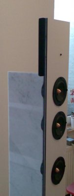
Let us have a strong, slim 'backbone' of wood or steel or other material. Attach the drivers by their magnet structures to this spine, of course, keeping in mind the offsets needed to keep their acoustic centres in line--so far as possible. See that the fixture profiles are slim so that they do not mar the rear radiation.
This structure has an added advantage: the weights of the drivers mostly act straight down and so keep the 'spine' (with a substantial base--make it an open tray and fill it with some concrete) balanced mechanically.
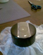
Now take baffles (you can have the baffles for the LF, MF and the HF units cut into separate, but 'matched-to-each-other' pieces) and cut the requisite holes for front radiation, with needed chamfering etc. Now obtain some round, tube-like rubber auto door trim (which often has a flat edging also), and fabricate round gaskets for each driver. Judicious application of a sharp craft knife and just one drop of super-glue and a steady hand is known to work miracles. Stick the gaskets to the driver baskets with soft-drying rubber-based glue.
Work out a method of mounting the baffles onto the 'spine' in such a way that by tightening the mounting screw you can adjust how far the gaskets get compressed. DO NOT over-tighten; you are looking for just an air-seal. Be sure to maintain say a small spacing between the individual baffles, say a quarter inch. Stick thick rubber strips to 'link' the baffles and ensure an 'acoustic continuity'.
Mounting the baffles onto the spine is important. And you can device and use 'shock mounts' to minimize the transference of vibrations from the spine onto the baffle. It is easier than stopping the baffles being vibrated with a vengeance by an active driver basket.
Let me know how this has worked for you. This is the only way I know by which you can tame the 'vibes'. You can reach me at ukpanickar@yahoo.co.uk, but be sure to put the subject line 'vibes'. Happy vibes to all OBers.
First off, let me say that I am not here to shout what everyone else is doing is NOT right. Rather, the attempt is to try and address the problem of baffle vibration from another practical angle.
An examination of current practices, amateur and pro, shows the drivers mounted onto the baffle, in this case a thick plank of mostly wood, sometimes matrix, concrete etc. Gravity is pulling at the magnet structure and even small mid or HF units will load the baffle with tension. Feed in a signal and add some vibration and we have a sure formula for (unwanted) trouble.
What's the alternative?
Let us have a strong, slim 'backbone' of wood or steel or other material. Attach the drivers by their magnet structures to this spine, of course, keeping in mind the offsets needed to keep their acoustic centres in line--so far as possible. See that the fixture profiles are slim so that they do not mar the rear radiation.
This structure has an added advantage: the weights of the drivers mostly act straight down and so keep the 'spine' (with a substantial base--make it an open tray and fill it with some concrete) balanced mechanically.
Now take baffles (you can have the baffles for the LF, MF and the HF units cut into separate, but 'matched-to-each-other' pieces) and cut the requisite holes for front radiation, with needed chamfering etc. Now obtain some round, tube-like rubber auto door trim (which often has a flat edging also), and fabricate round gaskets for each driver. Judicious application of a sharp craft knife and just one drop of super-glue and a steady hand is known to work miracles. Stick the gaskets to the driver baskets with soft-drying rubber-based glue.
Work out a method of mounting the baffles onto the 'spine' in such a way that by tightening the mounting screw you can adjust how far the gaskets get compressed. DO NOT over-tighten; you are looking for just an air-seal. Be sure to maintain say a small spacing between the individual baffles, say a quarter inch. Stick thick rubber strips to 'link' the baffles and ensure an 'acoustic continuity'.
Mounting the baffles onto the spine is important. And you can device and use 'shock mounts' to minimize the transference of vibrations from the spine onto the baffle. It is easier than stopping the baffles being vibrated with a vengeance by an active driver basket.
Let me know how this has worked for you. This is the only way I know by which you can tame the 'vibes'. You can reach me at ukpanickar@yahoo.co.uk, but be sure to put the subject line 'vibes'. Happy vibes to all OBers.
...
What's the alternative?
Let us have a strong, slim 'backbone' of wood or steel or other material. Attach the drivers by their magnet structures to this spine, of course, keeping in mind the offsets needed to keep their acoustic centres in line--so far as possible. See that the fixture profiles are slim so that they do not mar the rear radiation.
...
Agreed.
")
Attachments
Open Baffle Vibration
LineArray,
I like your strong, slim 'spine'. But from the pic, the mounting details cant be seen.
My take is that floating the baffle independently of the drivers is going to give you great dividends. Just try it on one channel and hear the difference!
A few days back I read some complaints about the baffle vibrations, but I was not watching which thread it was. Let us a have a real re-think on the open baffle. Great vibes to all.
OB vibrations
LineArray,
Checked out the German area and had a look at the pics. Your idea is good, as natural stone (marble, granite etc) or concrete is the way to go if u want to deaden vibrations. It was my choice also on many occasions. But I guess it is a brute-force method. Design elegance should try to avoid any force, good or bad, I think ;-)
Also, your method of driver mounting is not clear from the photos. By the way, what have you done to overcome the driver interaction artefacts in your large line array? I am curious...
If you are using a set of drivers, large to small, then it is desirable to taper the 'spine' towards the top so that not much occlusion of the rear radiation occurs. A sandwich of stone and wood would give you some mounting ease, and rigidity.
Driver mounting is all important, I guess. Try holding any driver by its front basket and imagine how difficult it would be to counter vibrations, what with the bending moments caused by driver weight acting in one direction--down--compounding the problem. Now try holding it by the magnet structure and see the dramatic change. We can borrow from mechanical engineering and 'shock mount' the driver to the spine easily. Stick the highly pliant tube gaskets to the drivers and mount the baffles as precisely that-- 'baffle' only, and not a 'sounding board'. Compressing the gasket to provide just an air seal is enough. Also, since the baffle/s is/are mounted to the spine, there is no transference of vibrations to it directly from the driver. Here also, with some ingenuity, 'shock mounting' techniques for the baffle can be adopted.
I would urge you to modify one channel so that the drivers are supported mainly at the magnet, and the baffle is 'floating'. Your ears will be 'opened' ....
Happy vibes!!
Hello,
Both the marble "spine" as an inertial vibration damper and the baffle are no
massive structures but two layered sandwiches utilizing a special sealant as
a contraint layer.
The construction does not rely on the properties of a single material solely.
The spine and the rigidly spine-mounted drivers , make up a standing "Pendulum"
of defined subsonic resonance frequency and damping, which is achieved by a
bearing in the foot of the speaker decoupling spine and baffle from the foot.
That bearing/damping is mainly made from cork and is fairly invisible.
The pics on the site are no documentation of mounting ...
but see below.
The construction you see is an answer to that question, the question has been
asked by myself before construction.
With rising frequency the output power is shifted towards the upper
- non equidistant - driver trio.
Interference patterns vary very smoothly with frequency and/or the listeners
vertical position, movement horizontally is even less a problem.
Subjectively very little change is observed when moving your head
vertically. The arrangement is superior to an equidistant arrangement and
has in fact much less interference problems than common 2-ways.
I know that this may be (very) hard to believe until you do some
simulations and finally listening tests and measurements which such
an arrangement: The driver distances have been optimized excessively.
It is not even peaking - comb filtering - if you put the microphone
on the bottom in 1m distance to the baffle ... which is not a typical
listening position.
There is of course a loss in brillance if you listen sitting on the
bottom and too near.
But the high quality listening area ist quite large with that speaker.
I am 44 Years of age now, but i guess up to now my ears are quite open still ...
The baffle is attached with only one of its constituent layers to the baskets
using damping sealant and grummets.
The second - rear side - layer of the baffle is "floating".
This way 3 things things are achieved:
1) High damping in the frequency region, where the baffle could
resonate from being accelerated by "rest forces" acting through
the baskets (Though the system is very quiet at mid to high frequencies).
2) Utilizing the stiffness of the spine to have a rather thin
(important in this concept) baffle, which is nevertheless rigid
(by beeing suported) enough to stay calm due to excitation by
low frequency sound pressure.
3) Having a baffle of less than 1/2 thickness near the rear
part of the basket, which yields maximum openness for
the rear basket side by having staggered driver cutouts in both
baffle layers.
To summarize: Since i have this speaker as a reference my own
standards of what is possible especially in non resonant bass to
lower midrange region, which is a problem with many cabinets
or open baffles, have moved into regions which are
not achievable with standard construction methods.
Concerning "clean" bass to mid region, this speaker truly opens
the ears of almost any listener ...
The listening room is the weakest part concerning modal
behavior in the bass region.
Kind Regards
...
Your idea is good, as natural stone (marble, granite etc) or concrete is the way to go if u want to deaden vibrations.
It was my choice also on many occasions.
But I guess it is a brute-force method.
Design elegance should try to avoid any force, good or bad, I think ;-)
...
Both the marble "spine" as an inertial vibration damper and the baffle are no
massive structures but two layered sandwiches utilizing a special sealant as
a contraint layer.
The construction does not rely on the properties of a single material solely.
The spine and the rigidly spine-mounted drivers , make up a standing "Pendulum"
of defined subsonic resonance frequency and damping, which is achieved by a
bearing in the foot of the speaker decoupling spine and baffle from the foot.
That bearing/damping is mainly made from cork and is fairly invisible.
...
Also, your method of driver mounting is not clear from the photos.
...
The pics on the site are no documentation of mounting ...
but see below.
...
By the way, what have you done to overcome the driver interaction artefacts
in your large line array? I am curious...
...
The construction you see is an answer to that question, the question has been
asked by myself before construction.
With rising frequency the output power is shifted towards the upper
- non equidistant - driver trio.
Interference patterns vary very smoothly with frequency and/or the listeners
vertical position, movement horizontally is even less a problem.
Subjectively very little change is observed when moving your head
vertically. The arrangement is superior to an equidistant arrangement and
has in fact much less interference problems than common 2-ways.
I know that this may be (very) hard to believe until you do some
simulations and finally listening tests and measurements which such
an arrangement: The driver distances have been optimized excessively.
It is not even peaking - comb filtering - if you put the microphone
on the bottom in 1m distance to the baffle ... which is not a typical
listening position.
There is of course a loss in brillance if you listen sitting on the
bottom and too near.
But the high quality listening area ist quite large with that speaker.
...
I would urge you to modify one channel so that the drivers are supported mainly
at the magnet, and the baffle is 'floating'. Your ears will be 'opened' ....
...
I am 44 Years of age now, but i guess up to now my ears are quite open still ...
The baffle is attached with only one of its constituent layers to the baskets
using damping sealant and grummets.
The second - rear side - layer of the baffle is "floating".
This way 3 things things are achieved:
1) High damping in the frequency region, where the baffle could
resonate from being accelerated by "rest forces" acting through
the baskets (Though the system is very quiet at mid to high frequencies).
2) Utilizing the stiffness of the spine to have a rather thin
(important in this concept) baffle, which is nevertheless rigid
(by beeing suported) enough to stay calm due to excitation by
low frequency sound pressure.
3) Having a baffle of less than 1/2 thickness near the rear
part of the basket, which yields maximum openness for
the rear basket side by having staggered driver cutouts in both
baffle layers.
To summarize: Since i have this speaker as a reference my own
standards of what is possible especially in non resonant bass to
lower midrange region, which is a problem with many cabinets
or open baffles, have moved into regions which are
not achievable with standard construction methods.
Concerning "clean" bass to mid region, this speaker truly opens
the ears of almost any listener ...
The listening room is the weakest part concerning modal
behavior in the bass region.
Kind Regards
Attachments
Last edited:
btw. the spacing of the upper 3-4 drivers was inspired by
"golomb ruler" spacings, which have an application e.g.
for the positioning of antennas in an array used for
radio astronomy. At least this was the starting point.
In a golomb ruler non repeating distances are used
for all marks (objects). The distances used for the upper
drivers in the "dipol 08" array are unique and as an additional
property mostly prime to each other.
Concerning bass output an equidistant spacing like the
larger distances of the bottom drivers would have a slight
advantage, but it would also exhibit serious comb filtering.
A correction network helps padding down the equidistant part
of the array, when entering the frequency range where comb
filtering would show up in an ugly manner.
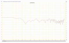
The plot attached shows FR on the BOTTOM in front of the baffle
in approx 1m distance. Since the height of the reference axis of the
speaker is betweeen the 2. and the 3. driver from above, this means
the measurement is from ~45 degrees of axis vertically ...
The plot is unsmoothed. Above 500Hz the level is reduced due to
the directivity of the array in vertical direction, but the typical
"line array comb filtering" does not occur : It occurs neither on- nor off axis.
For those interested in golomb rulers:
Golomb ruler - Wikipedia, the free encyclopedia
"golomb ruler" spacings, which have an application e.g.
for the positioning of antennas in an array used for
radio astronomy. At least this was the starting point.
In a golomb ruler non repeating distances are used
for all marks (objects). The distances used for the upper
drivers in the "dipol 08" array are unique and as an additional
property mostly prime to each other.
Concerning bass output an equidistant spacing like the
larger distances of the bottom drivers would have a slight
advantage, but it would also exhibit serious comb filtering.
A correction network helps padding down the equidistant part
of the array, when entering the frequency range where comb
filtering would show up in an ugly manner.
The plot attached shows FR on the BOTTOM in front of the baffle
in approx 1m distance. Since the height of the reference axis of the
speaker is betweeen the 2. and the 3. driver from above, this means
the measurement is from ~45 degrees of axis vertically ...
The plot is unsmoothed. Above 500Hz the level is reduced due to
the directivity of the array in vertical direction, but the typical
"line array comb filtering" does not occur : It occurs neither on- nor off axis.
For those interested in golomb rulers:
Golomb ruler - Wikipedia, the free encyclopedia
Attachments
Last edited:
OB vibrations
Line Array,
Thanks for that detailed reply. I can see that you have done excellent work. I am 57 and it looks like my ears have been opened! The appearance of your OB led me to believe that the drivers were bolted to the baffle, and surely even with gaskets and grommets, it would excite some unnecessary and noticeable vibes, and hence my humble suggestion for some mods. But your 'sandwich' technique has licked it I guess.
I noticed the unequal spacing of the drivers, but didnt know the methodology of your approach. Your expertise and knowledge in other fields (Golomb etc) has indeed come in useful. I am, like many ought to be, curious of the way you solved the interaction artefact problem. Do publish a more detailed approach so that all of us can benefit further.
Are you epoxying the driver magnet structures to the spine, or is that a kind of holder for the magnet?
All said and done, from the excellent results you have achieved by now, it is plain that a more detailed presentation is going to benefit the fraternity, I am sure. Especially as we are keen about your crossover techniques. And what is your experience about the rear radiation, its desirability, level, frequency domain etc. Looking for a more detailed presentation from you,
Sincerely, as always.
Hello Prof,
yes, magnets a are glued directly to the stone using a mix which
stays flexible a bit ...
To provide a "generalized" aproach or algorithm for the design is not that easy, because
it is a strategy mix and the actual cocktail depends on what you want to achieve.
The "strategy mix" used here has nothing new under the sun concerning its ingredients,
but the combination of strategies may be a bit uncommon.
Weighted line arrays are already common, and this one falls for sure into that category.
The weighting of drivers in a line array can be by power distribution between the drivers
or by distance between the drivers used. The "acoustical weight" rises where the drivers
are mounted closer or are supplied with input power increased relatively compared to their
neighbour drivers.
---
The first idea for "dipol 08" was to combine a frequency dependant power weighting and
weighting by distance, to make the array shorter with rising frequency more effectively.
This also helps in getting along with low order filters and smooth phase shifts while
doing so.
Dipol 08 is not meant to be a virtually infinite line source and is not a
"nearfield line array". I mention this to circumvent the "this is not a line array"
discussion which had evolved sometimes ...
Since the driver distance cannot be made frequency dependent, there is a "pre weighting"
by distance. Of course the relative to wavelength driver distance varies with frequency.
So up to some hundred Hz there is no real difference between dipol 08 and a fully
occupied dipole array of same height in behavior concerning directional radiation.
---
The second idea is to have the power weighting in a way that you get "nested" line arrays
which shrink in size (and number of drivers) as frequency rises.
In this case we start with all 6 drivers in the bass and end up with 3 in the highs.
The design can be consequently altered to reduce the array to a single driver in the
brillance region. Since the dipol 08 crossover network is a passive one currently, this has
proven impractical, the drawbacks are larger than its benefits.
(KISS keep it stupid simple ...)
Using an active configuration with each driver having its own power amp, reduction to a single
driver could/would be a consequent step. Then the reduction of drivers with frequency would go
like this (driver numbered from top to bottom):
654321
...321
....2.
The second driver from above would be the acoustic center for high frequencies.
De facto the current approach is already very close to that. The sound is subjectively
centered somewhat below the second driver from above, the array does not sound "smeared"
along its height:
654321
...321
Power tapering or "shading" is also not new entirely, the usual approch is to pad some of the
outer drivers down with rising frequency, so the array shrinks at its ends with frequency rising.
Since i wanted the acoustic center at ear height, i chose to get rid of the lower drivers as
frequency rises. Also there is not only downpadding, but the voltage transferred to the
upper drivers also rises above ~4Khz. This is to compensate for the missing contribution of the
downpadded drivers on the one hand, but also for compensation of the non sufficient energy radiated
in the highs from the fullrange drivers themselves.
I think you see, how things interact: The crossover network compensates also the driver
and has to be aligned for the particular driver used, as things are for every other loudspeaker
concept.
---
The third idea in the cocktail can be fuzzily described as follows:
When the driver distances come into the order of wavelength i want "golomb like"
spacings to "soften" the interference patterns. So the nested array active at a certain
frequency should have a "golomb ruler similar" spacing.
This is the idea behind it, not the real object which resulted during development.
As i said golomb rulers were a starting point in using unique distances.
For the upper 3 drivers a golomb ruler of 3. order would have the distances
0-1-3 position on ruler (marks)
1 2 3 driver number
for the drivers 1,2,3 when counting from the top.
Hence the distances between the drivers are
dr1 dr2: distance 1
dr1 dr3: distance 3
dr2 dr3: distance 2
A golomb spacing ensures unique distances for acoustic centers of each driver pair.
Broadly speaking: If two drivers interfere destructively at a certain listening
position, the third one will probably fill the notch.
But as the distances have common factors, there are still interferences causing peaks
and deep notches under certain angles although things are already better than using
equidistant spacings. *
To get a first solution, the arrangement was optimized using a software simulating frequency
response for different angles. Optimization was aimed at having the frequency response
varying as smoothly as possible in the range of vertical angles relevant for sitting and
standing persons at desired listening positions.
The minimum listening distance assumed will determine the range of angles, which are in the
main focus of optimization. I chose about 1.5 meters as far as i remember. The driver positions
have been varied randomly but keeping tuple distances unique.
First the whole array was undergoing optimization - it would also work rather well
without frequency dependant power tapering - then the "nested" array was "fine optimized"
for the range above ~2 Khz, since the uper 3 drivers dominate the presence to
brillance region.
Furthermore the 12 drivers have been selected according to serial tolerances:
Every driver knows his individual place in the array. A driver with some more
irregularities in the top end - or a rather "dull" candidate - qualifies as
"bass" not as "tenor" ... it is that simple.
Left and right speaker have to be made as similar as possible, this was also taken into
account for selection.
This was some effort, but i am convinced it made things a lot easier in the end, and
contributed to a - rather - simple correction network/crossover, because the
charcteristics of individual drivers were used to balance each other to some extent.
But this is really going into fine detail.
---
As i started out i could not say whether this approach would result in a homogenously sounding
speaker, although i was confident because it was not the first time for me going into that
direction.
Many listeners do the following test with that speaker intuitively without
being asked to do do it (its amazing!):
They stand up at their listening position and start to "knee bend" ...
up and down slowly - sometimes a bit faster - and the usual comment is:
"There is no change!" This is not what is usually expected.
In fact there is change ! It is fun watching the spectrum slowly
wiggling while leading a microphone over different vertical angles.
But it wiggles softly enough, it is sufficiently good for being
undetected subjectively while just listen to music.
Also knee bending is allowed (at home) but not necessary while listening ...
Like in every speaker i would do some changes for the next time.
The height of the reference axis is little bit too high, so small persons
- especially when sitting close on a low sofa - have a slight drop at the
top end.
They mostly do not burden, but i know its there. Usually i tilt the speakers
very slightly forward for them, then it is fixed.
Maybe the next time i will downsize it a little bit ("Lady Edition") ...
Kind Regards
-----------------------
* There is a rule of thumb also mentioned in a paper on nearfield line arrays
by Jim Griffin, that the coverage of the line array with radiating
surface should be at least 80 percent in an equidistant array to resemble
an ideal line source in a sufficient manner.
Unfortunately the paper does not seem to be available on the net currently:
Design Guidelines for Practical Near
Field Line Arrays
James R. Griffin, Ph.D.
It is obvious, that using fullrange drivers 80% occupation cannot be
achieved for high frequencies, even when mounted basket to basket or
slightly "overlapped".
This is because the radiating area of the cone breaks up and narrows
effectively with frequency rising. To approach the needed coverage
of the area, typical nearfield line arrays use a separate tweeter
line source.
My goal was having fullrange drivers solely and no crossover frequency
like present in a 2-way line array, which is likely to cause
irregularities in the horizontal plane ...
In the design patterns introduced by the US architect
Christopher Alexander
Christopher Alexander ? Wikipedia
it is mentioned as common solution, that a design constraint that cannot be met,
should simply be dropped. This often/mostly yields better results than trying
to meet the constraint in a half-hearted way.
With "Dipol 08" i did not even try to achieve that occupation of area, resulting
in a reduced number of drivers needed for the height of the array (about 1/2).
In turn also the "large number of cheap drivers" conflict is avoided governing
the cost of a conventional line array. The idea is to invest the budged saved
into better drivers if possible.
There are two further aspects, which should be mentioned:
When moving down with frequency, the drivers grow closer together acoustically
due to distance getting smaller compared to wavelength.
That compensates partly the falling radiation resistance with frequency
due to the open baffle design.
There is still need for some compensation, but much less is needed than usually
would be necessary for such a narrow baffle.
The lower cutoff is somewhere between 65 and 80 Hz according to the room
and position. I use the speaker as satellites with a mono subwoofer,
high passing them at 80Hz 1. Order.
They have no "dipole peak" in the upper bass which would need compensation.
During design the bottom reflections were taken into account by
"mirroring" the array at the bottom:
There is a second "dipol 08" under the floor, as an acoustic mirror image,
you just don't see it.
Optimization for low frequencies took the mirror image into account
while varying the driver spacings.
Kind Regards
Last edited:
OB Vibes
LineArray,
That was one good, solid read! Thanks for the patience to sit down and tap out all that--which in many places was pure Greek to me! I shall try to digest all that and come to a better understanding, I hope.
Perhaps you'd be kind enough to tell me if my idea of the spine stability and baffle decoupling was a step in the right direction so as to reduce unwanted colourations.
Personally I am not aiming for a full-range. My attempt will be to have --at least initially-- dual subs say, upto 150 Hz or so, acting as speaker stands, and have a 'transparent' OB for the rest of the FR. I am biased against having crossovers in the 200 Hz to about 3000 Hz band for obvious reasons. In a way, the 'voicing' of the speaker will be determined by the main driver handling this range.
My positive experience with the D'appolito array and its lack of distracting lobing in the vertical plane has jogged me in another direction--again, based on my observations and feelings. Most of the listening takes place in a sitting position, with a vertical 'range' that is just enough to take care of average body stature variations. But the problem with most speakers is the very narrow 'sweet spot' --which I wish to avoid. This is essential if one wishes to listen in company, which requires a wider 'sweet plane'.
Dont you think the D'appolito array on its side will present a wider sweet area for listening? Further, my feeling is that angled sides (rather than a U-shaped baffle) preserves smoothness of response--in fact many such studies exist. Confining myself to the limited range reduces vibration intensities too, I think. I would also think of a second tweeter facing the back to preserve the typical OB sound. I am even toying with using glass (coated with some silicon as a damper) as a thin and light baffle, decoupled from the driver fronts and anchored to the spine.
With your extensive experience I am sure you are in a position to offer some constructive comments/advice. If you have the time (and the inclination!), I would welcome a personal mail, so that we could discuss related points without sidetracking from the forum thread. (My id is: <ukpanickar@yahoo.co.uk> ) I sure would like to 'tap your brain' so that I do not foolishly bark up the wrong tree in my (over)enthusiasm! Thanks in advance....
Sincerely
...
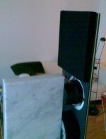
I would also think of a second tweeter facing the back to preserve the typical OB sound.
....
Sincerely
Agreed
.This is the rear tweeter panel, comprising 2 neodymium tweeters ...
picture is taken during some tests.
I will email you some thoughts.
Attachments
I considered the spine option and rejected it in favor of swinging dipoles; have a look at StigErik and mige0's build threads in the multi-way forum, particularly the smoothness of StigErik's SPL results. The magnet mounting I tested with was on the crude side, but my measurements agreed with StigErik's; flatter SPL from hanging the drivers.Let me know how this has worked for you. This is the only way I know by which you can tame the 'vibes'.
OB vibes
Twest 820,
Thanks for your response.
I was quite aware of StigErik's and Mige0's approaches. Horses for courses...if you feel comfortable with swinging speakers, those are the ones you should have!
But it will be criminal if I dont underscore the fact that my approach was meant to take care of the situation when a baffle WAS used--after all, open baffle is basically about the baffle. Mige0 has suspended the baffle and the driver together, thus taking out relative vibratons. Has he tried taking a contact microphone to the baffle and see how it sounds, how loud it probably sounds? What I have said probably has nothing to do with StigErik's approach, I guess.
My attempt was to only try and point some of the open baffle aficionados to a certain solution to the basic problem of baffle vibrations. As I did mention in one of my earlier posts, success comes when we treat a baffle as just that, and not as a 'sounding board'. Have you considered the fact that quite a few of the subjectively sweet-sounding speakers owe their 'sweetness' to the baffle vibes masking the mediocre drivers?
Personally I will try not to go in for a mechanically finicky and inherently unstable arrangement like the swingers, because I have always felt that our audio equipment should exist in the average real-world living rooms and work in that environ to transport us to a credible semblance of the recorded venue, and do that with simplicity and with the minimum of 'high-priestly' attention of continual 'setting-up' and other pampering. It would be nice if it could also co-exist with women and children and pets, and provide some entertainment to them too!
Experimentation and putting together of many heads is surely the pathway to progress. I am happy being in the midst of so many different kindred voices.
Sincerely.
Not to my knowledge; so far as I know mige0's not currently using the non-contact baffle.Has he tried taking a contact microphone to the baffle and see how it sounds, how loud it probably sounds?
Yes, that's why I opted to switch from box speakers to dipoles and eschewed a baffle on the dipoles. For magnet mounted baffled dipoles Jon Marsh's Isiris isn't a bad starting point.Have you considered the fact that quite a few of the subjectively sweet-sounding speakers owe their 'sweetness' to the baffle vibes masking the mediocre drivers?
My experience is hanging drivers takes considerably less effort than building baffles and magnet mount spines, so it's not clear to me why hanging drivers is mechanically finicky in comparison to other solutions. I guess stability's a bit subjective, but my swinging dipoles are in my rather average and certainly real world living room and have been just fine over the four months or so since I threw them together.I will try not to go in for a mechanically finicky and inherently unstable arrangement like the swingers, because I have always felt that our audio equipment should exist in the average real-world living rooms
OB Vibes
Twest820,
I will surely check out Jon Marsh's design as I am not familiar with it. I totally agree with a person's following what he perceives as the right combination of what all could work for him/her.
About the instability etc, you forget that you are a hobbyist audiophile. It may not look to be a stable and easy to handle design to others. That was my point.
Think of yesteryear's 'finicky' vinyl record players and even the reel-to-reel tape recorders; they were surely not for the casual or the ham-handed who just wanted to listen to music. If you can refine the suspension design to such a level as to make it usable for anybody, so that just moving around the speaker wont make you break out in cold sweat etc, then I would adopt it. This is not meant to prove anything, just that for the time being, I would look for other, less radical solutions!
Happy listening!
snip
My positive experience with the D'appolito array and its lack of distracting lobing in the vertical plane has jogged me in another direction--again, based on my observations and feelings. Most of the listening takes place in a sitting position, with a vertical 'range' that is just enough to take care of average body stature variations. But the problem with most speakers is the very narrow 'sweet spot' --which I wish to avoid. This is essential if one wishes to listen in company, which requires a wider 'sweet plane'.
Dont you think the D'appolito array on its side will present a wider sweet area for listening? Further, my feeling is that angled sides (rather than a U-shaped baffle) preserves smoothness of response--in fact many such studies exist. Confining myself to the limited range reduces vibration intensities too, I think. I would also think of a second tweeter facing the back to preserve the typical OB sound. I am even toying with using glass (coated with some silicon as a damper) as a thin and light baffle, decoupled from the driver fronts and anchored to the spine.
With your snip
Nothing could possibly be as HORRIBLE to the eye as those graphs of lobing. But do they have any effect on the ear? They are a snapshot of a single frequency and not of a musical sound. If these horrible charts would be rather different as tones change and heads move millimeters (not to mention when people with TWO ears are listening), it paints a different picture where there real world of live music and reproduced music is heterogeneous and sounds fine.
Of course there is tweeter beaming and "sweeter" spots vertically and horizontally and sometimes pretty narrow. But I doubt if the complex multi-lobe charts mean much.
Big arguments over in Geddes' territory about displaying directivity (not to mention establishing how important or not it is).
You are quite right about not cutting the passbands in wrong places. Funny how trivial issues become important while basic issues are forgotten. Like making ideal directivity with a two-way system sliced in half at the wrong place. I am lucky to have ESLs which give good wide-band performance and so crossover at 110 and 3200.
The build thread on the Isiris is over at HTGuide. Should turn up easily on a search but if you need a link let me know and I can dig it up.
There's also no requirement a swung speaker follow the traditional pendulum approach StigErik, mige0, and I all used. One option that's mechanically a bit complex in managing the resonant frequency but attractive for lightweight drivers like tweeters is an inverted pendulum made of light bar or rod stock. Another option is a pantograph. Simplifies getting the resonance down to a low frequency but comes at the expense of a more complicated build and some good bearings. Structurally it's pretty elegant. In particular if it's a counterbalanced pantograph the pantograph becomes the spine for magnet mounting and you arguably have the best of both worlds.
A third option is to magnet mount the driver on some sort of thrust bearing. Strictly speaking a driver on a thrust bearing is no longer a swung speaker but underlying idea's the same and the approach is attractive for heavy drivers which need a compact mounting. For example, if you want a spine style point source dipole you're going to wind up with something big such as a couple of 15s on an 18 near the floor. In that situation there's not enough room to make a weighted pantograph arm or inverted pendulum long enough for the resonance to be below the subs' working frequency. But putting a thrust bearing on a plinth is no problem.
If one feels a need for greater stability or ease in handling there's a variety of options. Tethering conventional pendulums, using inverted pendulums, or placing travel stops and locking mechanisms on pantographs or thrust bearings are the ones which immediately spring to mind. Another approach I've considered is simply to make it easy to dismount and mount the drivers on their swings but so far that's never seemed particularly compelling.
Really? I'd be curious to know the evidence you reach this conclusion from. It does seems to me that, as this is a DIYAudio thread, it's reasonable to assume the majority of folks who'll be reading it are, as you put it, hobbyist audiophiles. So it's probably reasonable to treat producing a swung speaker which would be commercially viable in the hi-fi market as out of scope to this thread. That said, I'm not aware of any technology limitations which would block the production of such a swung speaker. Or a nude one, for that matter; there's no requirement a nude speaker be swung or vice versa.you forget that you are a hobbyist audiophile
There's also no requirement a swung speaker follow the traditional pendulum approach StigErik, mige0, and I all used. One option that's mechanically a bit complex in managing the resonant frequency but attractive for lightweight drivers like tweeters is an inverted pendulum made of light bar or rod stock. Another option is a pantograph. Simplifies getting the resonance down to a low frequency but comes at the expense of a more complicated build and some good bearings. Structurally it's pretty elegant. In particular if it's a counterbalanced pantograph the pantograph becomes the spine for magnet mounting and you arguably have the best of both worlds.
A third option is to magnet mount the driver on some sort of thrust bearing. Strictly speaking a driver on a thrust bearing is no longer a swung speaker but underlying idea's the same and the approach is attractive for heavy drivers which need a compact mounting. For example, if you want a spine style point source dipole you're going to wind up with something big such as a couple of 15s on an 18 near the floor. In that situation there's not enough room to make a weighted pantograph arm or inverted pendulum long enough for the resonance to be below the subs' working frequency. But putting a thrust bearing on a plinth is no problem.
I'm sure there are some folks who'll feel that way though so far no one who's seen my build has had that reaction---mostly it provokes a good bit of curiosity along the lines of "I've never seen a speaker like that, what are you up to?" The hanging method I used is less secure than mige0's or StigErik's and it's really no problem to pick up the speakers and walk around with them. They can be a bit awkward to carry when the woofers get to swinging but that's easily avoided by taking a little care to move smoothly. It's different but I'd say it's less hassle than maneuvering a traditional plinth weighted box speaker around. Certainly less grunt work.It may not look to be a stable and easy to handle design to others.
If one feels a need for greater stability or ease in handling there's a variety of options. Tethering conventional pendulums, using inverted pendulums, or placing travel stops and locking mechanisms on pantographs or thrust bearings are the ones which immediately spring to mind. Another approach I've considered is simply to make it easy to dismount and mount the drivers on their swings but so far that's never seemed particularly compelling.
OB Vibes
My dear Twest820, you seem to have read me wrong.
Yes, we are all hobbyist tweakers for whom any sound arrangement that solves a particular problem is more than welcome. But we often in our eminently justifiable enthusiasm carry ourselves to extremes, and for us that may be the norm. But not so to many others. My comparison with vinyl turntables and the spool tape recorders of the previous era brought the point home, I guess. No quarrel about the effectiveness or the desirability of your( and others') swinging driver tech.
Personally I approach hi-fi from an angle that makes some presuppositions. First, solutions should be simple and elegant, and should appeal to (if not totally satisfy) the maximum range of interested people. Another basic thing about my approach is that imaging and clarity that pervades a wider area than the typical 'sweet spot' in an average 'normal room' takes precedence over other considerations like absolute fidelity, frequency response, or even a little bit of distortion.
As many commendable workers in the field have time and again pointed out, a subjectively satisfying reproduction of 'recorded reality' depends on many factors, but some such as the above are prime. The fallacy that many share about the desirability of an almost totally anechoic listening environment to achieve fidelity is something that has led many astray in their search for realism in reproduced sound events. Psychoacoustics has revealed that delays ARE essential if our ear-brain combo has to interpret what comes out of the speaker/s as something else that is far more 'real'.
Personally I dont mind if my FR is a tad less, if my lows dont hit the absolute bottom stop, or even if I suspect I could hear some sporadic distortion. But I'm distressed if I find that the reproduced image is not even vaguely 'credible'. I know and accept that the music is playing in my small living room using mediocre and low-powered equipment and in a not so perfect environment, where there can be absolutely no hope of approaching the real performance in its many qualities including dynamics and the 'being there' factor. Ah, but then I feel that hi-fi should be about giving a vast number of enthusiasts with a range of gear the feeling of 'almost being there'; the degree of feeling will surely differ, but the feeling should be there unequivocally. Without that, whatever might be your certified FR, dynamic range or calibrated SPL or whatever, will have failed to achieve what it set out to do-- and that too most miserably.
This is my take. What do you say, friends? Or am I being an ogre with a steamroller or worse? Sorry for the longish unburdening of my mind, but we live in a world of commercial realities and the fast sell. It is to get away from all that we are here. But while here we must constantly guard against mixing up our priorities. I am willing to be corrected by my peers--if I am wrong.
Good vibes to all, OBers and others!
Most sincerely.
OB Vibes
Bentoronto,
Hi Ben, I can see that you are a 'senior' hobbyist. From Canada? I love those Definitive Tech speakers I had heard...
While agreeing with you totally about how much of a double-edged tool measurements can be, perhaps I should say that more often it guides one in making informed design choices, and avoiding certain pitfalls.
I for one (I am not an engineer) did not know why certain speakers sounded the way they did, and why their imaging was so 'unsteady'. Lobing was the factor. And then there were related problems caused by crossover artefacts that exaggerated the uncertain behaviour of speakers as the frequency shifted up and down. Today I think we have a better understanding of such phenomena, thanks to measurement. What about simulation software? Again the same double-edged situation. But sims give us unmatched abilities to try out many things, and most of the time with educative outcomes too.
I loved the D'appolito in the vertical arrangement as being fairly non-critical; but when I turned it on the side, thinking that it would improve the spread of the 'sweet spot', I didnt know what happened, but things went haywire. So, onto sims and measurement and some guesstimates before putting wood and chisel together.
My feeling is that cutting and dicing in important areas is a no-no--unless of course you are a first rate surgeon! The 200 Hz--3,000 Hz range can easily be handled by any good driver, and that leaves you with a very good 'presence' range. Cross over to an unobtrusive tweeter without steep slopes in your filters and the 'brilliance' part is taken care of. If you can find a way to integrate an LF unit with a shelving response to take care of 'room gain' also, I think by then you have taken care of the whole range. Find a way so that your beautiful 'presence' speakers image well and truly and steadily, and according to this humble self, you ARE THERE, well, almost, of course, depending on a few more, but comparatively less important factors. I would like to know what you think.
About the basic/trivial issue conundrum, I guess I have said enough in my previous post. Great vibes to you.
Sincerely.
- Status
- This old topic is closed. If you want to reopen this topic, contact a moderator using the "Report Post" button.
- Home
- Loudspeakers
- Multi-Way
- Open Baffle Vibrations