Hi
I would appreciate some feedback on my latest thoughts on a MLTL with Hivi D6.8 and SEAS 27TDFC.
I have been inspired by zaphaudio.com where he is combining a standard dome tweeter with a simple waveguide from MCM.
My idea is to use the same tweeter and waveguide and combine them with a pair of HiVi D6.8 in an MTM network.
I think I will aim for a crossover frequency at approximately 1.9 kHz. At that frequency I get a wavelength 7.1” witch the spacing between each driver shall fall bellow to avoid comb filter effects.
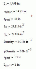
The cabinet is a straight mass loaded transmission line with a cros section of about 1.6*sd and 44” length. The port is 4” wide and 5” long placed close to bottom of the speaker.
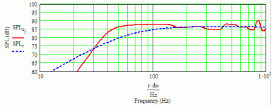
I have simulated with MJKs worksheets and with all room reflexions and get this in room response:
I am thinking of changing it though to 40” length and a sd of about 2, witch gives the same output but with a shorter box.
Do you think this could be a descent speaker or am I on the wrong path?
Regards
/Forsman
I would appreciate some feedback on my latest thoughts on a MLTL with Hivi D6.8 and SEAS 27TDFC.
I have been inspired by zaphaudio.com where he is combining a standard dome tweeter with a simple waveguide from MCM.
My idea is to use the same tweeter and waveguide and combine them with a pair of HiVi D6.8 in an MTM network.
I think I will aim for a crossover frequency at approximately 1.9 kHz. At that frequency I get a wavelength 7.1” witch the spacing between each driver shall fall bellow to avoid comb filter effects.
The cabinet is a straight mass loaded transmission line with a cros section of about 1.6*sd and 44” length. The port is 4” wide and 5” long placed close to bottom of the speaker.
I have simulated with MJKs worksheets and with all room reflexions and get this in room response:
An externally hosted image should be here but it was not working when we last tested it.
An externally hosted image should be here but it was not working when we last tested it.
I am thinking of changing it though to 40” length and a sd of about 2, witch gives the same output but with a shorter box.
Do you think this could be a descent speaker or am I on the wrong path?
Regards
/Forsman
Some folks would find the ~4th order roll-off this high up in frequency too under-damped ('boomy'/'loose') sounding so consider a T/S max flat alignment for a single driver, then add the second driver and tune it to ~flatten the lower impedance peak to see what this much better damped alignment looks like in-room at the listening position.
GM
GM
Hi GM
Many people on this forum and others recommend me not to tune the cabinet to low. The reason stated is that the bass risk to become loose and soft. Personally as the armature I am I don’t understand this properly. The transient response of a MLTL tuned to 45 or 30 Hz are to me almost identical.
Here is another shot, tuned a little lower.
Hight: 44”
Cross section area: 2*sd
Center of drivers from top: 11”
Port center from top: 40”
Port diameter: 3”
Port length: 5”
Stuffing: 0.3 lb/ft3 in the upper 2/3 of the pipe
Anechoic frequency response:
Do you think it is better to let it roll off lower like this?
/Forsman
Many people on this forum and others recommend me not to tune the cabinet to low. The reason stated is that the bass risk to become loose and soft. Personally as the armature I am I don’t understand this properly. The transient response of a MLTL tuned to 45 or 30 Hz are to me almost identical.
Here is another shot, tuned a little lower.
Hight: 44”
Cross section area: 2*sd
Center of drivers from top: 11”
Port center from top: 40”
Port diameter: 3”
Port length: 5”
Stuffing: 0.3 lb/ft3 in the upper 2/3 of the pipe
Anechoic frequency response:
An externally hosted image should be here but it was not working when we last tested it.
An externally hosted image should be here but it was not working when we last tested it.
Do you think it is better to let it roll off lower like this?
/Forsman
What a funny coincidence. I'm currently working with the exact same two drivers (D6.8 and 27TDFC) on a bookshelf size speaker. This is just a quick and simple vented 2-way though, nothing elaborate. I haven't measured anything yet though.
I thought the coincidence was notable considering how many drivers exist and the number of combinations that are possible.
..Todd
I thought the coincidence was notable considering how many drivers exist and the number of combinations that are possible.
..Todd
Last edited:
When I´m reading this section again I realize that I dont understand properly.consider a T/S max flat alignment for a single driver, then add the second driver and tune it to ~flatten the lower impedance peak to see what this much better damped alignment looks like in-room at the listening position.
Could you please elaborate on this matter a bit more? I would apprisiate it very much.
TrueWhat a funny coincidence. I'm currently working with the exact same two drivers (D6.8 and 27TDFC) on a bookshelf size speaker. This is just a quick and simple vented 2-way though, nothing elaborate. I haven't measured anything yet though.
I thought the coincidence was notable considering how many drivers exist and the number of combinations that are possible.
..Todd
")
What Xover point and order have you chosen?
Regards
/Fredrik
Many people on this forum and others recommend me not to tune the cabinet to low. The reason stated is that the bass risk to become loose and soft.
The transient response of a MLTL tuned to 45 or 30 Hz are to me almost identical.
Do you think it is better to let it roll off lower like this?
Greets!
Correct, me included since I normally recommend not going below ~0.707x Fs or ~38.8 Hz in this case (Fs with high output impedance amps) for simple reflexes (BR) since Fs is kind of an acoustic fulcrum point.
MLTLs that are acoustically long/large enough to significantly reduce a calculated length enough to increase the recommended BR vent size OTOH can be tuned down to this size since the cab proper is effectively acting as a large vent extension. As effective Qts, Vb increases and room gain is factored in, IME it's not uncommon to tune an octave or more below Fs and why I always recommend making the biggest cab that can be tolerated just to have as much tuning flexibility as practical.
WRT your specific alignment, it's mildly under-damped, so either adding some series resistance and/or more stuffing will perceptably 'tighten it up'. This sort of alignment tends to only work well though when well away from any boundaries in a room large enough not to have any appreciable gain in the speaker's pass-band.
GM
Take your design and change the driver specs to emulate two drivers and compare them to see what performance differences it makes, then adjust the vent length as required to further lower the lower impedance peak.
With 2x Sd and 0.5x the suspension compliance, it has much better acoustical damping, i.e. a way to get some of the benefits of compression horn loading without all the added build complexity/bulk. A byproduct is a roll off slope that usually blends with a room's acoustics much better than the max flat alignment.
GM
Thanks for your feed back GM!
I see that you have used the Fs published at zaphaudio.com. The official figure is 43 Hz and the measured figure on zaphs site is 55 Hz. (55*0.707=38.88).
To be able to simulate two drivers in the same enclosure I have modified the TS according to MJK paper Modeling Two Drivers In One Enclosure. The previous sims are also made that way.
I have increased the amount of stuffing to 0.5 lb/ft3 and its placed uniformly in the hole cab. The vent is now 7 in long. All other dimensions are the same.
Here is the same cab as above but 6 in shorter.
Even though it is shorter it still goes very deep in the bass.
And this is what happens when I reduce the cross section area to Sd*1.6 (237 cm2 * 1.6).
The last sim as .pdf.
Is this any better?
Regards
/Forsman
I see that you have used the Fs published at zaphaudio.com. The official figure is 43 Hz and the measured figure on zaphs site is 55 Hz. (55*0.707=38.88).
To be able to simulate two drivers in the same enclosure I have modified the TS according to MJK paper Modeling Two Drivers In One Enclosure. The previous sims are also made that way.
I have increased the amount of stuffing to 0.5 lb/ft3 and its placed uniformly in the hole cab. The vent is now 7 in long. All other dimensions are the same.
An externally hosted image should be here but it was not working when we last tested it.
Here is the same cab as above but 6 in shorter.
An externally hosted image should be here but it was not working when we last tested it.
Even though it is shorter it still goes very deep in the bass.
And this is what happens when I reduce the cross section area to Sd*1.6 (237 cm2 * 1.6).
An externally hosted image should be here but it was not working when we last tested it.
The last sim as .pdf.
Is this any better?
Regards
/Forsman
OK, now I think I understand what you mean GM.
First I took and modeled a MLTL for max flat alignment with one midwoofer. That turned out like this:
Number of mid wofers: 1
Hight: 44”
Cross section area: 1.83*sd
Center of drivers from top: 11”
Port center from top: 40”
Port diameter: 2”
Port length: 5”
Stuffing: 0.3 lb/ft3 in the upper 2/3 of the pipe
The I added the next midwoofer in parallel with the first without changing any other paramaters on the cab:
Number of mid wofers: 2
Hight: 44”
Cross section area: 0.91*sd
Center of drivers from top: 11”
Port center from top: 40”
Port diameter: 2”
Port length: 5”
Stuffing: 0.3 lb/ft3 in the upper 2/3 of the pipe
That gave us a pretty steep roll off. I then made the cross section a little bit wider, 1.13*sd:
That gave me a roll off with around 3-4 Hz/octave. Have I understood it correct that is a suitable roll off to blend in with the room gain.
I´m a bit concerned about chuffing from the vent. To use a 2” vent with two 6.5” drivers is less than I´ve read is recommended. In the worksheet there is a plot who tells us the port air velocity. MJKs recommendation is that port air velocity never should exceed 0.03. To that number I still have a margin of almost 20%.
But the cab is still pretty tall so I shortened it down with 6” and increased the cross section area to 1.3*sd. A lower cab but with almost identical response.
Number of mid wofers: 2
Hight: 38”
Cross section area: 1.3*sd
Center of drivers from top: 11”
Port center from top: 34”
Port diameter: 2”
Port length: 5”
Stuffing: 0.3 lb/ft3 in the upper 2/3 of the pipe
Have I got it right now?
regards
/Forsman
First I took and modeled a MLTL for max flat alignment with one midwoofer. That turned out like this:
Number of mid wofers: 1
Hight: 44”
Cross section area: 1.83*sd
Center of drivers from top: 11”
Port center from top: 40”
Port diameter: 2”
Port length: 5”
Stuffing: 0.3 lb/ft3 in the upper 2/3 of the pipe
An externally hosted image should be here but it was not working when we last tested it.
The I added the next midwoofer in parallel with the first without changing any other paramaters on the cab:
Number of mid wofers: 2
Hight: 44”
Cross section area: 0.91*sd
Center of drivers from top: 11”
Port center from top: 40”
Port diameter: 2”
Port length: 5”
Stuffing: 0.3 lb/ft3 in the upper 2/3 of the pipe
An externally hosted image should be here but it was not working when we last tested it.
That gave us a pretty steep roll off. I then made the cross section a little bit wider, 1.13*sd:
An externally hosted image should be here but it was not working when we last tested it.
That gave me a roll off with around 3-4 Hz/octave. Have I understood it correct that is a suitable roll off to blend in with the room gain.
I´m a bit concerned about chuffing from the vent. To use a 2” vent with two 6.5” drivers is less than I´ve read is recommended. In the worksheet there is a plot who tells us the port air velocity. MJKs recommendation is that port air velocity never should exceed 0.03. To that number I still have a margin of almost 20%.
An externally hosted image should be here but it was not working when we last tested it.
But the cab is still pretty tall so I shortened it down with 6” and increased the cross section area to 1.3*sd. A lower cab but with almost identical response.
Number of mid wofers: 2
Hight: 38”
Cross section area: 1.3*sd
Center of drivers from top: 11”
Port center from top: 34”
Port diameter: 2”
Port length: 5”
Stuffing: 0.3 lb/ft3 in the upper 2/3 of the pipe
An externally hosted image should be here but it was not working when we last tested it.
Have I got it right now?
regards
/Forsman
Last edited:
Hi bjorno
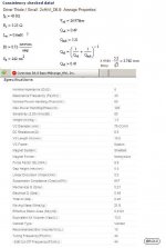
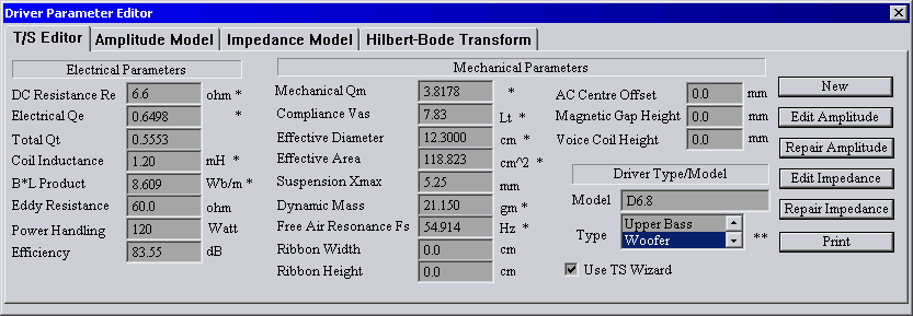
I´m not sure how reliable the official TS data are for the HiVi D6.8. I´ve used the TS data presented on zaphaudio.com where he has measured a couple of drivers.
the test
If zaphs data is any better I don’t know. I´ve tried to measure the drivers my selves with Arta Limp but with no success so far.
I have now two sets of data, the official and Zaphs, and I don´t know which is most true. Unfortunately they differ quite a bit so the discrepancy will probably make a significant difference in the response.
Before I do my final simulations and extract it to a drawing I need to measure the drivers properly.
This project so far is giving me the opportunity to learn a lot, even with TS full of flaws.
Regards
/Forsman
Last edited:
More data from PE (open the T/S file) HiVi D6.8 6" Poly Bass/Midrange Shielded | d6.8 6 inch woofer midbass woofer 6" driver sheilded woofer midwoofer poly cone22008 | Parts-Express.com
OK, plugging Zaph's specs into my MLTL calculator I get this (1st, 2nd scan) for a T/S max flat alignment. Plot when a second driver is added (3rd scan). Note the TL like roll off slope, so may only need vent fine tuning if room modes require it. Load into MathCad to see the increased damping, etc..
GM
GM
Attachments
If zaphs data is any better I don’t know.
I'll take his over the factory's any day. Bottom line for me, when there's more than one set of specs to choose from I use the ones that yields the largest cab since it's a lot easier to shrink a cab if required than stretch it. Not only that, but for my own designs I add some series resistance to further increase it just in case.
GM
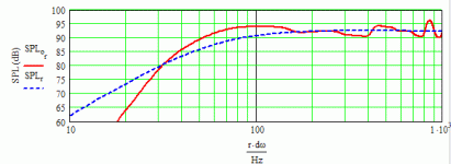
I´ve got exactly the same curves when I entered your parameters in my MathCAD. I guess I´m at least doing something right
I´m a bit puzzled about the spl response though. For me it seems a bit raged but on the other hand I have very little firsthand experience of how this curves will sound I reality. My reference so far is the small THOR and it´s curve looks like this:
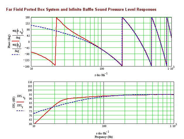
Picture borrowed from here
Is this kind of response desirable or has it also a too steep slope at the bottom?
I´m a bit puzzled about the spl response though. For me it seems a bit raged but on the other hand I have very little firsthand experience of how this curves will sound I reality. My reference so far is the small THOR and it´s curve looks like this:
Picture borrowed from here
Is this kind of response desirable or has it also a too steep slope at the bottom?
Thanks, now I have not two but three sets of TS data
Didn´t see that. Will do som more simulationg to see if I can create it.it should wind up being a more rounded off response.
- Status
- This old topic is closed. If you want to reopen this topic, contact a moderator using the "Report Post" button.
- Home
- Loudspeakers
- Multi-Way
- A try at MTM in MLTL configuration with HiVi D6.8