The MC4 bass unit isn't Rogers, it's an Audax MTX20X25TDSN; the tweeter is by TDL.
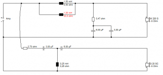
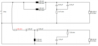
The tweeter X/O is third order electrical, 2R7 on the input, then 3mfd, 0.22mH, 6mfd. Bass is a weird kind of 2nd order - it has 9.87mH in parallel with a 1.2mH inductor which has 30R resistance - cap is 9mfd.
Strange you say they are bright - I found them a bit dull with some hardness around 4k and a suck-out 2-3k.
Thanks Zuhl, I just picked up these speakers off of ebay. I had a pair back in 1987 but sold them sadly. Now I am starting over again !
I think something is wrong with these for them to be bright as you say they are normally have a bassy balance.
If I renew the caps am I correct with:
2x 3.00uF 250 V and 2x 6.00uF 250 V for each xover. (I noticed up by the tweeter output ? on the xover the 3.00uF and the 6.00uF caps seemed to be connected together)
Last edited:
The bass had 6mfd and 3mfd in parallel to make 9mfd - and I forgot earlier, a 0R47 resistor in series - I'm doing this from memory and haven't seen the x/o for about 10 years...
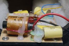
The bass x/o was connected with red and black wires, the tweeter x/o with thin yellow and blue wires.
The bass x/o was connected with red and black wires, the tweeter x/o with thin yellow and blue wires.
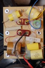
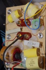
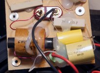
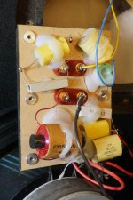
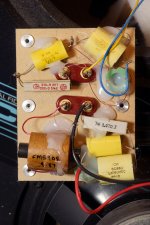
Ok guys, as promised photos of my MC4 (V1) crossover. Hope someone can make some sense of whats under all that glue")
What I'm coming up with is below. I'll ignore a 9.87mH coil. That makes no sense, it's too big a value. Maybe they've deliberately obscured the value.
It doesn't look like anything I've ever seen though. That 1.2mH coil with 30R resistance that Zuhl mentioned might be tailoring the bass crossover slope and phase a bit.
But it's really odd, IMO. Is that what it looks like to you BarbieBoy? See, I'd just expect a simple ca. 1.5mH coil here.
FWIW, the tweeter crossover looks totally standard, even down to being wired in negative polarity here.
BTW, I think I've drawn the RC (0.47R +9uF) shunt the wrong way round from your crossover.
Attachments
Last edited:
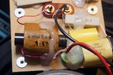
You can't see it on those images, but I have what's left of the crossovers I had here. The inductor says 9.87 on it - I have no way of measuring inductors, but it's a similar size to some 10mH I have in a sub x/o.
The 0.47R does go to the negative.
Interesting you have a single board. Mine had two boards: bass was glued in the bottom of the cabinet and the tweeter in the top rear of the cabinet.
The 0.47R does go to the negative.
Interesting you have a single board. Mine had two boards: bass was glued in the bottom of the cabinet and the tweeter in the top rear of the cabinet.

Well, we have a mystery on our hands then!
9.87 is bizarrely accurate, don't you think? 10mH is the preferred value.
Some measurements would help a lot here I think. But you need a good multimeter with a mH inductance scale.
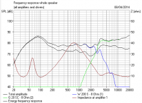
10mH bass coil does THIS to the frequency response in my VERY rough sim.
9.87 is bizarrely accurate, don't you think? 10mH is the preferred value.
Some measurements would help a lot here I think. But you need a good multimeter with a mH inductance scale.
10mH bass coil does THIS to the frequency response in my VERY rough sim.
Attachments
Very nice! Remind me, Barbieboy. What exactly is wrong with the sound?
If it is a straight 3dB tweeter reduction you want, which is quite a lot actually, this is how you'd modify it. That will sound a lot less bright at the top end.
The RC Zobel on it's own just rolls off the very top. Which helps metal tweeters IMO.
It's quite hard to pick out problems at crossover by ear though.
Attachments
Last edited:
Lack of bass or too much treble. If nothing is wrong with the xovers, then perhaps speaker cables have something to do with it. Using DNM cables which are said to be unforgiving, tried some silver wire and that was a little easier on the highs ironically as silver is also 'unforgiving'.
Hi,
9-87 is more likely a date code than inductor value.
I have some MC2's which use the same tweeter. I installed
some L-pad values so long ago I can't recall the values.
Series in probably 1R3 or 1R6, parallel probably 20R,
wired to the tweeter after the crossover.
FWIW the bass of the MC2's suffers with scrawny cables,
don't ask me why, I did loads of cable experiments with
them years ago, enough to form an opinion for them.
Nowadays I'd just recommend Richer Sounds cheapest
speakers cable. Strip it back both ends with one end
being very long and tin the copper with solder.
Alternatively use 4 core mains cable in a star format.
Forget bi-wiring just go the tweeter terminals first
and use the extended ends to connect the bass.
rgds, sreten.
FWIW my MC2 cables are solid core 3 x CAT5 plaited,
with all twisted pairs wired in parallel, no plugs, and
extended tails to connect the biwiring terminals.
I'd still rather recommend 4 core in star quad, though.
Last edited:
Yep, Sept 1987 is the cabinet's date stamp so makes sense.
Got a friend who just popped in said the sound is lean and bass light. Got them out into the room a bit I admit, move them back and bass increases but imaging goes to pot.
Biwiring opens up the soundstage, less muddled to my ears. Also solid core DNM interconnects which I have just taken out, way too much with using their speaker cables too. Only since getting these MC4s that has been a problem. Amp and source the same.
Will tackle the wiring last Sreten, never heard a bad word of recapping old gear, even new stuff ! Perhaps the caps have gone 'hard'
Hi,
...9-87 is more likely a date code than inductor value....
rgds, sreten.
HaHa, Genius!
What you do to increase the bass is add, say, 50% value to the bass coil and take a third off the capacitors in the bass circuit back to 6uF. The LC product stays the same, if you follow. This slopes them down more.
However, you then also need to increase attenuation on the treble. Phase shouldn't be affected too much.
But you'd need to know what the bass coil is by measuring it.
I suppose that odd little coil is what you call "secret sauce"... darned if I know why it's there!
Hi,
I don't think you'll get very far replacing any of the caps.
FWIW for my MC2's, which were the budget version of
the MC4's, which I have well out into the room as well
as the subtle treble reduction I've got some built in low
bass boost in my amp to work with the room gain.
Regarding biwiring, YMMV, for the MC2's though it had
notable effects it seemed to introduce discontinuity.
The MC4's are worth persevering with, by most
accounts the originals were very good with an
excellent midrange due to the TPX drivers.
TPX was hailed as the successor to poly,
but that clearly never happened, not
sure why, perhaps consistency ?
rgds, sreten.
I'd guess you could do a lot with those speakers over a period. As you say, sreten, nice 8" bass units, which I am coming to believe are as good as it gets as a basis for a useful two way. Hours of fun to be had.
The SERIOUS DIYer will shell out about £60 for a multimeter which can read Coils as well as caps and resistors. I got mine at Maplin:
That hot glue is a pain to get off. I melted mine off in hottish water, though I'm not sure what it does to components, and they seem to dry out OK. Hot Glue guns are standard sort of fare and don't cost more than a tenner.
You also need a hot 40W soldering iron these days with modern lead free solder. The old 25W jobbies don't hack it. Again Maplin have some cheap and cheerful ones. The trick, in a nutshell, is not to linger more than about 5 seconds when soldering. Work fast and hot.
Maplin don't stock coils. But have the rest of the components at highish prices. Probably Falcon Acoustics or Wilmslow Audio are worth checking out for a bigger order.
Having had another look at the sim, I'm guessing the bass coil is about 1.2mH with that 9uF capacitance for a near 3kHz crossover. I'd reckon 2mH and 6uF would be bassier, perhaps with an ohm or two in the shunt too. The little weird coil might as well go in the bin by my estimation. You'd then add 2-3 ohms to the treble filter input to balance it out in the simplest way.
Tweeter upgrades would be the most interesting. I won't mention the "C" word, but here's the Clue.
The SERIOUS DIYer will shell out about £60 for a multimeter which can read Coils as well as caps and resistors. I got mine at Maplin:
An externally hosted image should be here but it was not working when we last tested it.
That hot glue is a pain to get off. I melted mine off in hottish water, though I'm not sure what it does to components, and they seem to dry out OK. Hot Glue guns are standard sort of fare and don't cost more than a tenner.
You also need a hot 40W soldering iron these days with modern lead free solder. The old 25W jobbies don't hack it. Again Maplin have some cheap and cheerful ones. The trick, in a nutshell, is not to linger more than about 5 seconds when soldering. Work fast and hot.
Maplin don't stock coils. But have the rest of the components at highish prices. Probably Falcon Acoustics or Wilmslow Audio are worth checking out for a bigger order.
Having had another look at the sim, I'm guessing the bass coil is about 1.2mH with that 9uF capacitance for a near 3kHz crossover. I'd reckon 2mH and 6uF would be bassier, perhaps with an ohm or two in the shunt too. The little weird coil might as well go in the bin by my estimation. You'd then add 2-3 ohms to the treble filter input to balance it out in the simplest way.
Tweeter upgrades would be the most interesting. I won't mention the "C" word, but here's the Clue.
- Status
- This old topic is closed. If you want to reopen this topic, contact a moderator using the "Report Post" button.
- Home
- Loudspeakers
- Multi-Way
- replacement tweeters musical fideleity mc4 speakers