... with 2 fullrangers, and series passive xover, and an Amp 6 with current feedback 😀 (what an oddballs' party😛 )
OK, I'm cheating, I own the drivers already (stored for a while). So only the baffle was built, and this part is REALLY CHEAP 😀 I own the Amp 6 kit and the related parts for mod, too..
Basic setup is 2 x 8" widerangers per side and sort of 1.5-way -- the one on top plays fullrange and the bottom one joins somewhere below midbass. I tried series xover here -- just connecting a cap across the one for bass (short-circuit when frequency is higher then a point... ), and connect the 2 drivers in series.
Why?
I'd like to have a rising impedance towards the low end, and driven by a high Zo amp to form a 'natrual' compensation for the dipole loss. The two impedance peaks around fs add to a very high value, also very 'helpful' when working with high Zo amp.
So here they are:

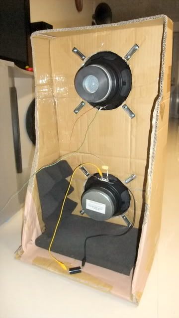
Oops, sorry for the bad picture...
Ah! this is much better:
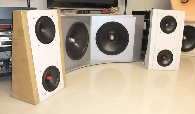
(note: the big woofers in V-shape baffle in the background are not included in this system)
LoL !! yes! cardboard baffles 😀 How can you beat that in cost! And they are even not in pair -- not the same color and even different in size. Guess I care ? 😀
Minimalism construction - partially destructed cardboard box, some glue and duct tape, done!
More later.....
OK, I'm cheating, I own the drivers already (stored for a while). So only the baffle was built, and this part is REALLY CHEAP 😀 I own the Amp 6 kit and the related parts for mod, too..
Basic setup is 2 x 8" widerangers per side and sort of 1.5-way -- the one on top plays fullrange and the bottom one joins somewhere below midbass. I tried series xover here -- just connecting a cap across the one for bass (short-circuit when frequency is higher then a point... ), and connect the 2 drivers in series.
Why?
I'd like to have a rising impedance towards the low end, and driven by a high Zo amp to form a 'natrual' compensation for the dipole loss. The two impedance peaks around fs add to a very high value, also very 'helpful' when working with high Zo amp.
So here they are:
Oops, sorry for the bad picture...
Ah! this is much better:
(note: the big woofers in V-shape baffle in the background are not included in this system)
LoL !! yes! cardboard baffles 😀 How can you beat that in cost! And they are even not in pair -- not the same color and even different in size. Guess I care ? 😀
Minimalism construction - partially destructed cardboard box, some glue and duct tape, done!
More later.....
you beat me to it - for some time I've been meaning to put all the old 8" drivers in my shed on a baffle made from cardboard - I can get cartons from work with sides 100x65 cm. Like the simplicity of the xover, let us know how it sounds...
Ok, some numbers and tweaking process:
This is the first time I try series xover. As mentioned above, I want high impedance towards LF, to work with high Zo amp. Since the impedance peak at fs is always there and can't be removed, especially in barely loaded dipole, so I'd like make use of it. Passive series xover configured in 1.5way makes the amp see two drivers in series, thus double the impedance (well, sort of). This enhances the interaction with high Zo amp in the way I want.

The R1 in parallel with upper driver is for attenuating it somewhat by sharing the current, and also reducing the overall impedance in this section, which attenuates it further. But too small of it would suck out the liveliness of the mid-high sound. Also a lower series R makes the lower cap bigger to maintain the proper low pass frequency for the lower driver. Howerver, too big a cap sucks too much current, makes the mid-bass weak. By the size of baffle (only 40 cm by 70cm, with some side wings as the picture), I was planning the join-in frequency of the lower driver in 150~200 Hz range. Eventually I couldn't get the target because of those dilemmas.
Dilemmas, all over🙁
The numbers above are the final compromise among drivers' characters, baffle size, sound quality... etc. By the way, I always feel a passive xover with severely padded down section(s) sounds dull. Resistors in series with drivers give zero good impression -- just a necessary evil, to maintain a proper balance. Now I find it almost equally annoying when using it in parallel.
How about ditch the resistor? I tried it but there's another problem. Two sections in series, then the one with higher impedance shares more voltage, thus more power. Since the dipole loss are huge in LF, so I need as much power as possible here, at least in a view of proportion.
Now these 2 drivers are not the same. Sigh~ but these are what I got on hand right now. The impedance measurements reveal a horrible fact that the one on top has a higher fs (but lower impedance peak). So you can see two peaks in the chart:
I can not get overlapped display on WT3's screen, so I exported the data and made a chart with separate driver's curves:
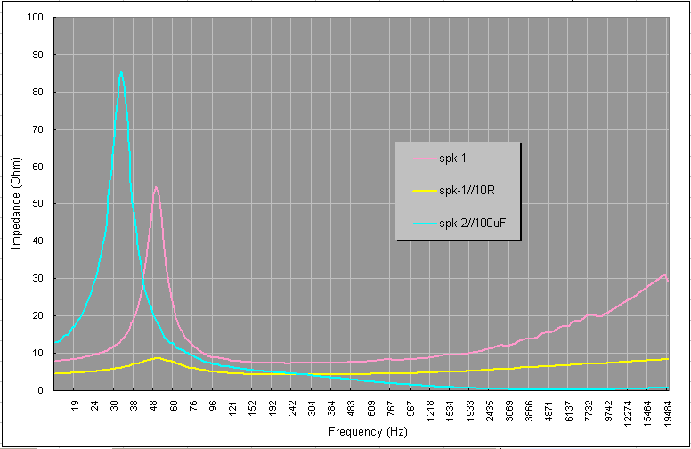
Here you can see, in the midbass range, how the upper one suck much more voltage than the lower one by its much higher imedance. However this driver has inherently lower sensitivity, higher fs and much dryer/thinner bass by ear, so it's a bad choise for the bass. Dilemma again.
This is another major reason of the parallel R - to damp the impedance peak and let the lower one get the larger share of the available voltage.
Tried and tried, I settled to 10R and 100uF, now the system impedance curve looks pretty much as I hope for.
Exported the impedance data (and the Zo of amp) to the spread sheet I made previously, I got the following result - about 10~12dB boost in bass (or attenuation to the midband in the same degree). And this is very close to the experience of previous without/with current feedback trial. I drew a 6dB/oct. line beside it for comparison. It seems the compensation by the 26 Ohm Zo of amp is still not enough.
At this stage, it's still too bass shy. By the upstream EQ, additional 12~18dB shelving filter helps in making it flat. (That's what it's still lacking)
Now another dilemma. The tested Amp 6 (with current feedback mod) doesn't have enough voltage gain to play with. The added current feedback also reduces its overal gain. I raised it by reconfiguring (enlarging) the original feedback resistor, but it brought me hiss. No big deal, though. Inaudible beyond 0.5m away with the 92dB/w driver. However it's enough to stop me increasing the gain and applying more current feedback.
I'm stuck. Where to get the additional 12~18dB? (more is needed when playing quietly in late night)
I want to get full digital resolution back, so I made a line level passive shelving filter by simple RC combinations, instead of relying on the digital EQ. Of course this also reduces the overall gain of the system, but I think it's a simpler, and better solution for sound quality.
Finally I managed to get a reponse like this, crudely measured at the listening position.
Subjectively, it's good to 40-some ~ 50Hz range. Limited by the available gain in the signal chain and low efficiency of dipole with small driver(s), it can't produce high SPL for sure, but obviouly much louder than the previous single pair pure naked setup.
And it's a very dynamic sound, with bouncy, punchy bass. So drums and bass notes are wonderful, not because they are cheap and little, they're really good. The senses of energetic are everywhere. Bowed bass is delivered with superb textures, as the loads of details in the rich mid and high. I think such quality should come from the Amp by a very large degree. In my memory these speakers with other amps didn't sound like this.
Oh, forgot to say, the drivers under test here were made and sold by a local shop with limited quantity. I played with them for some time and eventually modded them hard - whizzers on both were cut and several layers of PVA coating were applied to the cones. One of them got wood phase plug. Lack of whizzers, top end loses some sparkles, but I won't describe it a dark sound, just not so airy. A tad of lower mid coloration is detectable, somewhat 'woody' or 'chesty' in some materials. I'd guess this should be the baffle - pretty much the muffled sound when you tap the cardboard. Putting some foam pads on the inside walls around the U-shape base cures some...
Overall speaking, fast and fun aside, this project proves several things as I expected:
1. Passive series xovers are hard to get right, but have their unique strength when working with high Zo amp. (and potential to some kinds of array might be desirable... )
2. High Zo amp works in a wonderful, elegant way with OB speakers. And additional current feedback is doable even in full-bridged class D amp (or T here).
3. Making OB speakers out of small size drivers and baffles is a hard task. Compensation for baffle loss, dipole loss, low Q loss... are just too much. At first in the pure naked trial, total 40dB is needed to make it flat. Now in this setup, line level filter gives 18dB, current feedback give 12dB, unknown portions by 1.5way configuration and some baffle area (and floor) makes up the rest. In the end, I think this is a good practice to spread the 'loads' (of all these compensation) to different "stages" in the whole system.
This simple little project is for testing the concepts above. Maybe I'll build something more 'real' with better drivers and baffle construction (suspended...). Or maybe I'll fiddling with the class D amp for my main system first...
Oh, this is already too long...
This is the first time I try series xover. As mentioned above, I want high impedance towards LF, to work with high Zo amp. Since the impedance peak at fs is always there and can't be removed, especially in barely loaded dipole, so I'd like make use of it. Passive series xover configured in 1.5way makes the amp see two drivers in series, thus double the impedance (well, sort of). This enhances the interaction with high Zo amp in the way I want.
The R1 in parallel with upper driver is for attenuating it somewhat by sharing the current, and also reducing the overall impedance in this section, which attenuates it further. But too small of it would suck out the liveliness of the mid-high sound. Also a lower series R makes the lower cap bigger to maintain the proper low pass frequency for the lower driver. Howerver, too big a cap sucks too much current, makes the mid-bass weak. By the size of baffle (only 40 cm by 70cm, with some side wings as the picture), I was planning the join-in frequency of the lower driver in 150~200 Hz range. Eventually I couldn't get the target because of those dilemmas.
Dilemmas, all over🙁
The numbers above are the final compromise among drivers' characters, baffle size, sound quality... etc. By the way, I always feel a passive xover with severely padded down section(s) sounds dull. Resistors in series with drivers give zero good impression -- just a necessary evil, to maintain a proper balance. Now I find it almost equally annoying when using it in parallel.
How about ditch the resistor? I tried it but there's another problem. Two sections in series, then the one with higher impedance shares more voltage, thus more power. Since the dipole loss are huge in LF, so I need as much power as possible here, at least in a view of proportion.
Now these 2 drivers are not the same. Sigh~ but these are what I got on hand right now. The impedance measurements reveal a horrible fact that the one on top has a higher fs (but lower impedance peak). So you can see two peaks in the chart:
I can not get overlapped display on WT3's screen, so I exported the data and made a chart with separate driver's curves:
Here you can see, in the midbass range, how the upper one suck much more voltage than the lower one by its much higher imedance. However this driver has inherently lower sensitivity, higher fs and much dryer/thinner bass by ear, so it's a bad choise for the bass. Dilemma again.
This is another major reason of the parallel R - to damp the impedance peak and let the lower one get the larger share of the available voltage.
Tried and tried, I settled to 10R and 100uF, now the system impedance curve looks pretty much as I hope for.
Exported the impedance data (and the Zo of amp) to the spread sheet I made previously, I got the following result - about 10~12dB boost in bass (or attenuation to the midband in the same degree). And this is very close to the experience of previous without/with current feedback trial. I drew a 6dB/oct. line beside it for comparison. It seems the compensation by the 26 Ohm Zo of amp is still not enough.
At this stage, it's still too bass shy. By the upstream EQ, additional 12~18dB shelving filter helps in making it flat. (That's what it's still lacking)
Now another dilemma. The tested Amp 6 (with current feedback mod) doesn't have enough voltage gain to play with. The added current feedback also reduces its overal gain. I raised it by reconfiguring (enlarging) the original feedback resistor, but it brought me hiss. No big deal, though. Inaudible beyond 0.5m away with the 92dB/w driver. However it's enough to stop me increasing the gain and applying more current feedback.
I'm stuck. Where to get the additional 12~18dB? (more is needed when playing quietly in late night)
I want to get full digital resolution back, so I made a line level passive shelving filter by simple RC combinations, instead of relying on the digital EQ. Of course this also reduces the overall gain of the system, but I think it's a simpler, and better solution for sound quality.
Finally I managed to get a reponse like this, crudely measured at the listening position.
Subjectively, it's good to 40-some ~ 50Hz range. Limited by the available gain in the signal chain and low efficiency of dipole with small driver(s), it can't produce high SPL for sure, but obviouly much louder than the previous single pair pure naked setup.
And it's a very dynamic sound, with bouncy, punchy bass. So drums and bass notes are wonderful, not because they are cheap and little, they're really good. The senses of energetic are everywhere. Bowed bass is delivered with superb textures, as the loads of details in the rich mid and high. I think such quality should come from the Amp by a very large degree. In my memory these speakers with other amps didn't sound like this.
Oh, forgot to say, the drivers under test here were made and sold by a local shop with limited quantity. I played with them for some time and eventually modded them hard - whizzers on both were cut and several layers of PVA coating were applied to the cones. One of them got wood phase plug. Lack of whizzers, top end loses some sparkles, but I won't describe it a dark sound, just not so airy. A tad of lower mid coloration is detectable, somewhat 'woody' or 'chesty' in some materials. I'd guess this should be the baffle - pretty much the muffled sound when you tap the cardboard. Putting some foam pads on the inside walls around the U-shape base cures some...
Overall speaking, fast and fun aside, this project proves several things as I expected:
1. Passive series xovers are hard to get right, but have their unique strength when working with high Zo amp. (and potential to some kinds of array might be desirable... )
2. High Zo amp works in a wonderful, elegant way with OB speakers. And additional current feedback is doable even in full-bridged class D amp (or T here).
3. Making OB speakers out of small size drivers and baffles is a hard task. Compensation for baffle loss, dipole loss, low Q loss... are just too much. At first in the pure naked trial, total 40dB is needed to make it flat. Now in this setup, line level filter gives 18dB, current feedback give 12dB, unknown portions by 1.5way configuration and some baffle area (and floor) makes up the rest. In the end, I think this is a good practice to spread the 'loads' (of all these compensation) to different "stages" in the whole system.
This simple little project is for testing the concepts above. Maybe I'll build something more 'real' with better drivers and baffle construction (suspended...). Or maybe I'll fiddling with the class D amp for my main system first...
Oh, this is already too long...


- Status
- Not open for further replies.
- Home
- Loudspeakers
- Multi-Way
- Even Cheaper and Faster OB Trial