Hi all
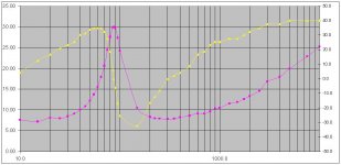
We are able to plot the impedance versus frequency of a speaker either in air or installed on an enclosure.
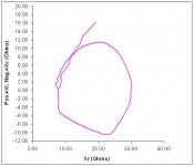
We can thus have a set of impedance parameters of this speaker for every frequency in Z (Ohm) and V to I Phase Angle (degrees) data, or in R, Zl, Zc (Ohms) and Zx to R Phase Angle (degrees).
Is it possible from all these data sets to reverse engineer (construct) the electrical network from L,C,Rs (equivalent circuit) which will exactly model this speaker in this very installation?
Best Regards
George
We are able to plot the impedance versus frequency of a speaker either in air or installed on an enclosure.
We can thus have a set of impedance parameters of this speaker for every frequency in Z (Ohm) and V to I Phase Angle (degrees) data, or in R, Zl, Zc (Ohms) and Zx to R Phase Angle (degrees).
Is it possible from all these data sets to reverse engineer (construct) the electrical network from L,C,Rs (equivalent circuit) which will exactly model this speaker in this very installation?
Best Regards
George
Attachments
Last edited:
Hello Dennis
Thanks for contributing.
One question please.
How do you manage to assign values to the electrical model constituents (Ohms on R, mF on C, mH on L), when your calculations –using the formulas at the bottom of the schematic- are in Length, Mass, Force ect?
I tried to use this h ttp://en.wikipedia.org/wiki/SI_derived_unit
Farad=m−2∙kg−1∙s4∙A2
Volt=m2∙kg∙s−3∙A−1
Ohm=m2∙kg∙s−3∙A−2
Henry=m2∙kg∙s−2∙A−2
But I don’t come to any meaningful units.
Nevertheless, even if I was able to assign values to the electrical symbols, this wouldn’t be the answer to my question.
For, this is fixed model ( I have seen others as well, representing speakers on other enclosure types), onto which one assigns values derived from calculations.
What I have asked is, if it is possible to derive a speaker electrical model from it’s impedance versus frequency data
Best Regards
George
Last edited:
So you have 2 sets of readings, one in free air and one in a sealed enclosure of known volume?
The impedance curves are already showing you something. You can see the free air resonant frequency fs
You can see the resonant frequency of the closed-box system fc
You can calculate Qts and Qtc. These are the ratio of reactance to resistance at fs and fc
From these you can calculate alpha = ((Qtc/Qts)^2) -1
You know the box volume Vb, so you can calculate Vas = alpha * Vb
You know RE
Some of the other parameters are directly measurable, such as cone effective area.
You can easily determine the cone mass by adding a weight and remeasuring fs. This, with the cone effective area A, the density of air and the speed of sound will tell you Cms. And so on... As you measure and calculate more values, you will get to cross check parameters. Once you determine values for the impedance simulation, you can compare the result with your measurements.
This isn't my field. Do you have Dickason's book? I'm just picking the maths out of it. Have a look on Rod Elliott's site too.
w
I don't know if there's any foolproof deterministic way to do this. I divide the curve up into regions like the resonant peak, figure out the Q, design a generic tank circuit, then scale it to the correct impedance. The rest of the curve is a slow rise at some dB/octave, so that's done similarly. No doubt there's some better way, but I just use the basic L-C formulas and charts in almost any edition of Terman. You do a model of a crystal in a similar manner and some of the values can be remarkably large. Check your results with a quick plot in LT Spice or similar.
Au contraire,
I found the Holy Graal ....
Bye
I found the Holy Graal ....
Wakibaki ,are you sure ??This isn't my field
Bye
Hi George
To convert between mechanical and electrical impedances, the "magic number" in the specs is BL.
BL = strength of magnetic field in the gap * length of voice coil wire in the gap
and BL = Force on diaphragm / current in voice coil
and BL = Induced voltage across coil / diaphragm velocity
So: Induced voltage / Current = BL * BL * Velocity / Force
~~~~~~~~~~~~~~~~~~~~~~~~~~~~~~~~~~~~~~~~~
To get back to your original question (if I understand it correctly): I think in general it could be extremely difficult or impossible to treat a loudspeaker system as a "black box" and derive the equivalent circuit purely from impedance measurements.
For simple systems e.g. sealed box or reflex, one could pick the appropriate "off the shelf" equivalent circuit and fill in the values.
For something like that shown below (a horn) it's not so easy. One could (with difficulty) invent an LCR circuit with similar impedance and phase curves, but it would not be equivalent - the transient behavior would be totally different.
Cheers - Godfrey
Attachments
Hello all
Thank you for your responses.
I have looked on the internet for a possible answer to my quest (which is as godfrey wrote “treat a loudspeaker system as a "black box" and derive the equivalent circuit purely from impedance measurements”.
My wish is, this electrical circuits that is born out of the measured electrical impedance of the driver/enclosure, to be used to study the effect that the value of each component has on the outcome. Also, to calculate/simulate the acoustic frequency response of this driver/enclosure..
There are some less demanding utilizations of this model, e.g. the study of the amplifier and/or x-over interaction with this model.
It seems that indeed all the software packets that deal with speaker/enclosure simulation, are adopting some electrical model of the speaker driver and some electrical model for the enclosure.
Alas, these models ( their structure and the components value ) are not “accessible” by the user.
I understand that even if the software packets were making their models accessible, the success would depend entirely on the precision (adequacy ?) of the embodied model.
Yes, there are some simulators, which predict the acoustic output of a certain speaker (modeled by entering it’s T/S parameters).
This prediction is OK but only for the bass range.
We may optimize the bass response using these simulators and the actual acoustic results may- in the bass range - follow the modeled response, but I have found in the proccess of building loudspeakers, that the midfrequency response (sound) may be dramatically affected while optimizing the bass range acoustic response.
The simulators do predict some changes in the midfreq. Range, but only through the harmonic series of the low resonance frequency of the speaker/enclosure system.
I do not think that this harmonic series is enough to explain the acoustic effect the enclosure imposes on the midfreq. Response of a speaker. I suppose that this is attributed to the lack of a very detailed equivalent circuit.
For example, I have seen on the various published speaker/enclosure equivalent circuits, the radiation acoustic resistance of the cone to be modeled by a resistive element. Isn’t this not an oversimplification (as much as is the use of a pure 8 Ohm resistor to model a real speaker as an amplifier load)?
What do you think? Are the published speaker/enclosure equivalent circuits detailed enough to let us model speakers over an extended frequency range, or there is a need for a more precise customized model generation ?
Best regards
George
Last edited:
...
For example, I have seen on the various published speaker/enclosure equivalent circuits, the radiation acoustic resistance of the cone to be modeled by a resistive element. Isn’t this not an oversimplification
...
Modelling loudspeakers with equivalent circuits always goes together
with simplification. In case of a conventional direct radiating dynamic
loudspeaker, it is sufficient to estimate the output measures like
cone velocity and excursion from the equivalent circuit.
A "BR-Enclosure with driver" equivalent circuit can e.g. be used to check
the maximum excursion being in sane limits for the particular driver, before
building the box.
The radiation of sound is a minor effect with such a loudspeaker. The
impedance results practically from the capacitors, inductors and resistors
in the circuit solely which represent the masses, compliances and mechanical
resistances "seen" by the moving voice coil.
Once the frequency dependent cone velocity is known, the radiation
(sound pressure or power) can be estimated, thereby taking
into acount the relative size of the cone compared to wavelength,
the mounting conditions of the driver in the baffle and the
position of the cabinet in the room.
Cabinet resonances above the fundamental resonance, cone breakup
and so on are usually neglected...
Even the voice coil inductivity is normally lossy and cannot be
represented by an inductor solely.
IMO a more complete equivalent circuit of a multiway speaker e.g.,
which includes at least the fundamental resonances of all drivers
and their voice coil inductivies, can be very helpful in designing a
good crossover. A passive crossover e.g. is then integrated into
the equivalent circuit as a whole. The prediction of the crossover
characteristics is much improved compared to modelling the
drivers as resistors only. Furthermore the effective impedances of
the builtin drivers can often be utilized, thereby allowing the
crossover to be made simpler.
A different philosophy is "compensate all you can" to make the load
resistive. Regardless which philosophy to follow, a good equivalent
circuit describing the main components of a speaker is a good start.
Every common circuit simulation software can be used for optimization
and refinement of the model by measured data.
Impedance data and electrical crossover slopes are easy to measure,
and are much more reproducable than acoustical measurements, where
conditions have to be kept constant over days or weeks, which is
not always possible unless you have a dedicated room for measurement.
The other way round, if your acoustic measurement or auditive
impression shows some flaws, a good equivalent circuit is helpful
in adressing the problem effectively by testing design changes
in your circuit simulator like "add some brilliance > 8 Khz",
"bring down Q of builtin midrange driver" and so on.
Best Regards
Basically with a single impedance run, you have too many unknowns and too few equations. You have to fix something somewhere. Ther are several things that you can do - fix the radiating area, fix the voice coil Re, but that still isn't enough. You have to fix somemore parameters, probably two more, and then the solution is unique. Otherwise there are an infinite number of solutions.
Basically with a single impedance run, you have too many unknowns and too few equations. You have to fix something somewhere
...
I am not sure if we are talking about the same thing.
When i measure the TS Parameters of the woofer and
the tweeter in a 2-Way e.g. i can model the impedance of the
drivers very closely, especially in case of the lossy VC
inductance being included for each driver.
When introducing the XO components now, the slopes predicted
from the model and those measured at the drivers terminals will
fit very closely in magnitude and phase, if the equivalent
circuit has been modelled well.
Also the frequency dependent impedance of the whole speaker
can be matched very well.
Frequency dependent directivity of the drivers, modal membrane
behaviour, baffle diffraction, room boundary reinforcement,
exitation of room modes - in short everything on
the mechanic to acoustic side - is completely out of scope of
such a model.
I never said something different. But when the electrical to
mechanical side is modelled with good accuracy,
it is much easier to find and turn the right screws on the
electrical to mechanical side, even in cases where the reason
for turning a srcrew comes from mechanic to acoustic behavior.
Of course if the reason for a certain flaw lies within the
acoustic radiation domain, like e.g. driver directivities not
matching at crossover frequency, the problem should be solved
at its roots by design.
The equivalent circuit which is a model of the electrical to
mechanical side of the speaker, is something like a blueprint to me,
where changes can be made rapidly in a "whatif" manner.
It does not substitute the work on the real object, but it helps IMO
in grabbing the right parts with interesting values out of the crossover
parts box.
I also often revised a circuit, which developed after various listening
and acoustic measurement, using equivalent circuit simulation.
It happens, that the sonic result improves, although this is not
guaranteed.
Regards
Last edited:
Geddes, didn't you develop a method to measure TS only by a current source and a voltage source, with the driver in free air?
I think I read it in a post by you long ago.
Three measurements - current, voltage AND pressure. Its all written in a patent - look it up at USPTO.gov
i accidently ran over this:
http://www.diyaudio.com/forums/mult...lee-summa-abbey-kit-build-32.html#post1729457
Seems i am not the only one, using that modelling approach
as an aid for crossover design. Equivalent circuit modelling and
interactive crossover design would maybe good stuff for a
dedicated thread.
http://www.diyaudio.com/forums/mult...lee-summa-abbey-kit-build-32.html#post1729457
Seems i am not the only one, using that modelling approach
as an aid for crossover design. Equivalent circuit modelling and
interactive crossover design would maybe good stuff for a
dedicated thread.
Frequency dependent directivity of the drivers, modal membrane
behaviour, baffle diffraction, room boundary reinforcement,
exitation of room modes - in short everything on
the mechanic to acoustic side - is completely out of scope of
such a model.
Regards
But you see all of the stuff that you list above is included in my models. Otherwise the models are not accurate enough, as my linked post says.
I was pretty sure, You would say that. There is no doubt, one can
attempt to include as much as possible.
For direct radiating speakers making a clear cut at the mechanic
to acoustic side is what makes equivalent circuits so very useful IMO.
In my opinion it is not useful to mix strongly coupled dependencies,
which can be modelled very accurate, with weaker coupled dependencies
which also change with - not always controlable - parameters outside the speaker.
If you don't mind to tell, which type of data do you have got usually to
describe modal behavior of membranes in terms of motional impedance
and radiation ?
If you don't mind to tell, which type of data do you have got usually to
describe modal behavior of membranes in terms of motional impedance
and radiation ?
What I do is a mix of experimental data and simulation and quite honestly the techniques are proprietary.
There are far better models than lumped parameter - I haven't used that approach for decades. I guess I can only recommend my book if you are still using LRC circuit type models as these are seriously limiting. Its not that the "break", as you describe it, is convenient as much as it is necessary. With Matrix methods this break need not be made at alll.
Hello all
What do you think? Are the published speaker/enclosure equivalent circuits detailed enough to let us model speakers over an extended frequency range, or there is a need for a more precise customized model generation ?
Best regards
George
Thiele/Small type approaches will only ever deal with the first few octaves of a woofer/box's response. They also can only be accurate for a pretty ideal case. Not in 2 pi: not so good. Cone break up: not considered. Woofer inductance: not included, could be added seperately.
We are always comparing the LF region to a 2nd (or 3rd or 4th) order high pass filter. Very useful as far as it goes, but the model doesn't extend beyond the corner.
David
- Status
- This old topic is closed. If you want to reopen this topic, contact a moderator using the "Report Post" button.
- Home
- Loudspeakers
- Multi-Way
- What a *@#$%^& Idea! Shoot him!