For those that are interested, I intend to show build progress of my 20:1 taper TL, which since design conception has undergone several changes. The original design and simulations of response are here:
http://www.diyaudio.com/forums/multi-way/158116-my-visaton-tqw-tube-speaker-eventually-started.html
http://www.diyaudio.com/forums/multi-way/158116-my-visaton-tqw-tube-speaker-eventually-started.html
design evolution.
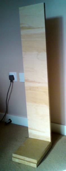
due to constraints in (mainly) my woodworking skill, and also a few random improvisations, the design idea changed from this:
to the revised, ie easier for me to build, version:
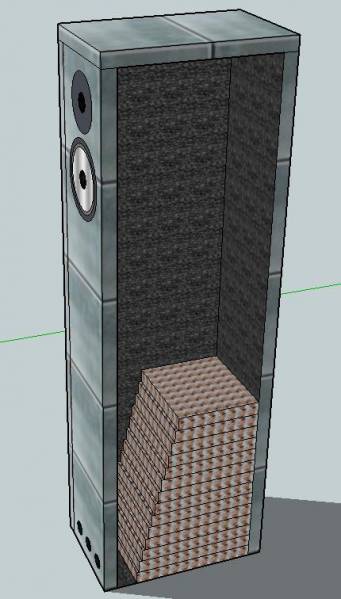
note: the lam sections do carry on to the top of the 'box' although i couldnt be bothered to draw them all in!
due to constraints in (mainly) my woodworking skill, and also a few random improvisations, the design idea changed from this:
An externally hosted image should be here but it was not working when we last tested it.
to the revised, ie easier for me to build, version:
note: the lam sections do carry on to the top of the 'box' although i couldnt be bothered to draw them all in!
the tapered lam part of the design uses 39 lams of 1" MDF, the depth of these lams is reduced by 6mm each lam. This was a bit of a compromise and WILL lead to the last few lams being 24,18,12,6mm deep.
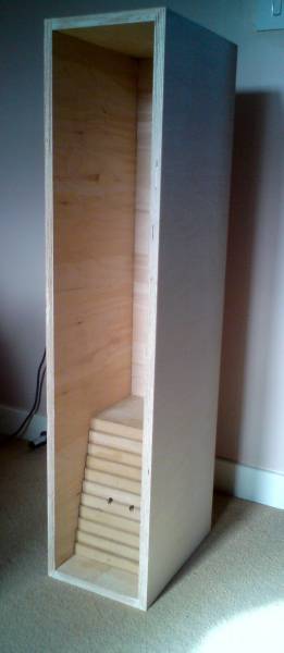
this was where my thinking ran out of steam and the design was improvised. The last few lams are planned to be cut from sections of thin ply 1" wide, and stacked up to get desired depth.
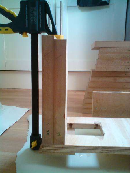
a section was cut from 5 lams to allow fitment of the xover within a rear cavity towards the bottom of the box:
The 'stepping' of the lams can be seen here:
this was where my thinking ran out of steam and the design was improvised. The last few lams are planned to be cut from sections of thin ply 1" wide, and stacked up to get desired depth.
a section was cut from 5 lams to allow fitment of the xover within a rear cavity towards the bottom of the box:
The 'stepping' of the lams can be seen here:
Last edited:
to MDF or to Birch ply, that is the question...
originally, i had planned to use MDF for construction of the design, in all panels.
However, when i got to the DIY store, they were fresh out of 1" MDF. In a fit of frenzy and in eagerness to actually get this project rolling, i quickly recalculated sizes for 18mm stock instead.
While doing this, i thought that it would be worth looking a b&q's 'best quality' birch ply. As it was ungraded i was unsure of quality, but its probably fair to say it isn't b/bb grade, and the good veneered side had a couple of small plugs.
However the idea that a good sand and varnish would be all that was needed to finish the ply was appealing, since i didn't and still don't relish the idea of sanding, priming, sanding, painting, sanding, lacquering, sanding sanding sanding MDF to get a good finish.
So it was settled, birch ply it is. £60 and one 8x4' sheet, 30 mins and a bemused cutting guy later, (who broke the saw twice) i had my panels.
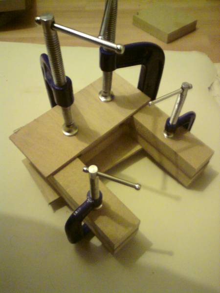
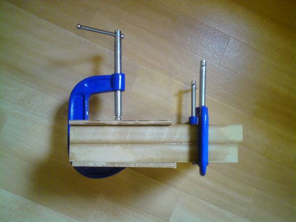
next i started with the glueing:
And next with some of the lams in place, pending more jigsaw time, and dust proofing of the kitchen/workshop.........the OH will hate me
originally, i had planned to use MDF for construction of the design, in all panels.
However, when i got to the DIY store, they were fresh out of 1" MDF. In a fit of frenzy and in eagerness to actually get this project rolling, i quickly recalculated sizes for 18mm stock instead.
While doing this, i thought that it would be worth looking a b&q's 'best quality' birch ply. As it was ungraded i was unsure of quality, but its probably fair to say it isn't b/bb grade, and the good veneered side had a couple of small plugs.
However the idea that a good sand and varnish would be all that was needed to finish the ply was appealing, since i didn't and still don't relish the idea of sanding, priming, sanding, painting, sanding, lacquering, sanding sanding sanding MDF to get a good finish.
So it was settled, birch ply it is. £60 and one 8x4' sheet, 30 mins and a bemused cutting guy later, (who broke the saw twice) i had my panels.
next i started with the glueing:
And next with some of the lams in place, pending more jigsaw time, and dust proofing of the kitchen/workshop.........the OH will hate me
Last edited:
next the xover
The AL130, like many AL cone drivers has a characteristic peak of quite large amplitude at breakup, around 7k of around 8-10dB.
after initial searching on the web i found that several of the visaton kit projects used both the AL130 and G20SC that i am using in this project. relying on specs sheets only i would say that the g20sc is far and away the best tweeter (at least available to me) except the KE20 ceramic dome, which i couldnt find a supply for in blighty.
i intended to use the 'vib130tl' crossover design as found here:
http://www.visaton.de/bilder/weichen/gross/vib130tl_w.gif
the vib130tl design as a whole is quite interesting, but i wanted to make a tapered line using the MJK based excel sheet on qw.com, so i downloaded Boxsim, to see if i could optimise the xover for my application, and baffle geometry.
after much work i tweaked a few values and added a coil to tame the breakup peak a little more, and improve the response about 5k.
I came up with this:
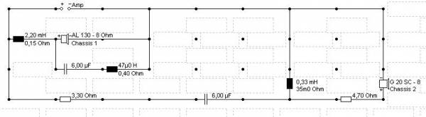
I used high current rating ferrite cored inductors, rated at 5A or more (against the purist air core philosophy), as from my experience in rotating m/c testing I knew that saturation and non linearity would only occur at higher currents than this in these particular coils. also, the smaller external EM field would mean a more compact board could be made without the risk of mutual coupling.
the response, in my application, went from this:
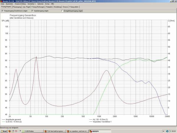
to this:
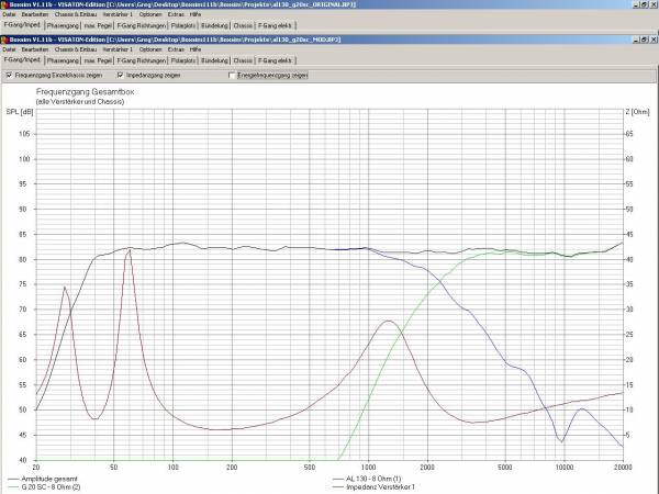
The AL130, like many AL cone drivers has a characteristic peak of quite large amplitude at breakup, around 7k of around 8-10dB.
after initial searching on the web i found that several of the visaton kit projects used both the AL130 and G20SC that i am using in this project. relying on specs sheets only i would say that the g20sc is far and away the best tweeter (at least available to me) except the KE20 ceramic dome, which i couldnt find a supply for in blighty.
i intended to use the 'vib130tl' crossover design as found here:
http://www.visaton.de/bilder/weichen/gross/vib130tl_w.gif
the vib130tl design as a whole is quite interesting, but i wanted to make a tapered line using the MJK based excel sheet on qw.com, so i downloaded Boxsim, to see if i could optimise the xover for my application, and baffle geometry.
after much work i tweaked a few values and added a coil to tame the breakup peak a little more, and improve the response about 5k.
I came up with this:
I used high current rating ferrite cored inductors, rated at 5A or more (against the purist air core philosophy), as from my experience in rotating m/c testing I knew that saturation and non linearity would only occur at higher currents than this in these particular coils. also, the smaller external EM field would mean a more compact board could be made without the risk of mutual coupling.
the response, in my application, went from this:
to this:
Last edited:
xover construction.
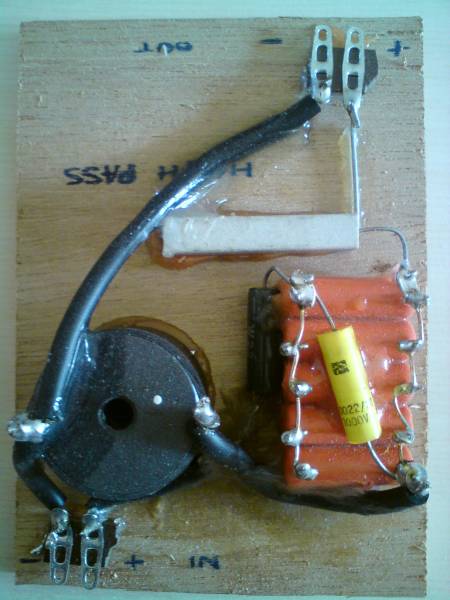
i mounted the components on a a piece of ply about 4x5" using epoxy glue and securing all vibratable wires eetc with silicone rubber sealer:
high pass board:
low pass board:
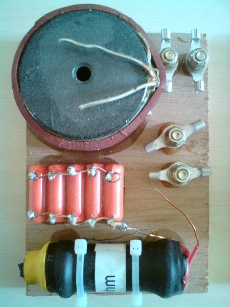
NOT SHOWN: pics show 5uF caps made up of 5x1uF in a bank, with a .0022uF added to the top. In the design these are meant to be 6uF, but in fairness i havent added them to the board yet!
all caps are 1000v rated polyester film, and the .22uF is 1500V PP film type, as i got them in a bargain clearout for about 5p each as opposed to 60p for the same cap at 5uF and 250V rating.
the additional coil, the 47uH, .4 Ohm one, was wound by hand on an m12 60mm bolt, using .6mm enamelled wire. I used about 30ft, then using a RCL bridge reduced the length until the right value was reached. the DCR of .4 Ohm is little to worry about seeing as its not in the series path of the woofer. In fact the fully modified design i WAS going to use a 0.47Ohm resistor following the inductor in the parallel path, to widen the notch. This gave a virtually picture perfect roll off, however i decided to omit it as the impact was very minimal on the response of the system as a whole.
i mounted the components on a a piece of ply about 4x5" using epoxy glue and securing all vibratable wires eetc with silicone rubber sealer:
high pass board:
low pass board:
NOT SHOWN: pics show 5uF caps made up of 5x1uF in a bank, with a .0022uF added to the top. In the design these are meant to be 6uF, but in fairness i havent added them to the board yet!
all caps are 1000v rated polyester film, and the .22uF is 1500V PP film type, as i got them in a bargain clearout for about 5p each as opposed to 60p for the same cap at 5uF and 250V rating.
the additional coil, the 47uH, .4 Ohm one, was wound by hand on an m12 60mm bolt, using .6mm enamelled wire. I used about 30ft, then using a RCL bridge reduced the length until the right value was reached. the DCR of .4 Ohm is little to worry about seeing as its not in the series path of the woofer. In fact the fully modified design i WAS going to use a 0.47Ohm resistor following the inductor in the parallel path, to widen the notch. This gave a virtually picture perfect roll off, however i decided to omit it as the impact was very minimal on the response of the system as a whole.
Last edited:
birch ply Vs MDF?
at this point ill stop to mention the virtues or non virtues, as i see it, of birch ply.
pros:
the ply looks nicer than MDF
It smells better too
its heavier and certainly tougher (the cutting man broke the saw on it)
cons:
compared to MDF the panels sounds like drum, without any bracing, so im not sure about ply advocates 'stiffness' arguement. with ply im going to have to use alot of damping and bracing to nullify this, where in MDF i wouldnt have to, or to a lesser extent. Im planning on using some steel 8x50mm section tube i have lying around to strengthen it.
its a pain in the bum to NOT chip the top veneer, so the finish will not be perfect. although it will still look better than MDF and save me the effort required to finish MDF well.
compared to MDF the panels sounds like drum, without any bracing, so im not sure about ply advocates 'stiffness' arguement. with ply im going to have to use alot of damping and bracing to nullify this, where in MDF i wouldnt have to, or to a lesser extent. Im planning on using some steel 8x50mm section tube i have lying around to strengthen it.
Isn't this due to the resonance of the material being pushed up due to the stiffness? If you use a "soft" material, the resonance is lower so may not be audible with a knuckle rap. But, the energy is lower higher up, so there is benefit to this...less energy at the resonance to make it resonate. Not that bracing is a bad idea.
Looks good! Building it this way, the back and sides are surely going to be very solid, since they are basically solid! So it's mainly the baffle you'll need to work on keeping well braced and non-resonant, mabye the top too.
I used LBL on part of my front baffles, bonded onto MDF. I obtained it from these:
Kitchen Craft Bamboo Chopping Board, 31 x 46 x 1.8 cm: Amazon.co.uk: Kitchen & Home
It is the most solid part of the cabinet, producing a higher tone with a shorter decay when knocked on, compared to the ply laminated to MDF which the rest is built from. It isn't big enough for the whole top of mine, I just used it where the drivers mount. May be worth considering, it is nice to work with too, just don't touch any rough cut edges!
compared to MDF the panels sounds like drum, without any bracing, so im not sure about ply advocates 'stiffness' arguement. with ply im going to have to use alot of damping and bracing to nullify this, where in MDF i wouldnt have to, or to a lesser extent. Im planning on using some steel 8x50mm section tube i have lying around to strengthen it.
It may be too late now, but I would have considered constrained layer damping (green glue and two layers of birch).
The problem with bracing is that it stiffens the walls (which is good), but what you really want to do is dissipate the acoustic energy into heat - I think.
This looks like some form of transmission line variant, so I can't speak to what works best in that situation. It looks like you have some tiny ports at the base of the cabinet. Normally, for vented cabinet they look too small and transmission lines usually have larger openings, so I am in the dark here.
There are self stick butyl rubber sheets you can buy like Damplifier Pro that may help. However, a cheap alternative is to staple two layers of roofing felt onto the interior surface of the cabinet walls. You can give that a try first to see if that reduces resonances.
One inexpensive trick for testing the cabinet is to buy an acoustic guitar pickup that mounts beneath the bridge of the guitar. You can hot melt glue that pickup onto the outside cabinet wall and use that like a microphone to measure the cabinet wall vibration and resonances just like you would if you were using a mic to measure the cabinet frequency response.
This way you can measure and see relative improvements with things like damping material, roofing felt, and bracing.
thanks all
thanks for the comments.
@Dr.EM:
IM hoping that you're right,I too think that by the time i have all the layers glued up, the sides will be very dead indeed. At the moment the aren't since the majority of the panel is unbraced...but not for long!
Nice idea about the chopping board....MAY do that if have time.
@Loren:
Yes it is a TL variant, a tapered TL in fact. the vent area is about 3in[squared]. This will be divided into up to 6 holes of 20mm diameter. That way i can finalise tuning by the use of stuffing and also vent area (if necessary).
Im planning to use 'brown bread' damping material, which if you havent used, is basically a bitumous sheet, with a layer of foil on the top. I usually iron it on so that it softens and bonds well with the wood underneath.
CLD is defo out of the question at this point, and to be honest, its a bit of a pain to employ effectively, and also a bit much for my modest wood working skills. Although i COULD have used silicone to glue the sides to the internal lam sections and probably achieved the effect as a by-product. i didnt think of that at the time though...
I have access to velocimeters/accelerometers and vibration measurement equipment at work so i might take the finished speakers to work on day and measure the panel modes.
Last edited:
its been a while, so a little update for those that havent lost interest entirely!
Well, with one thing or another, my build has ended up going to schedule about as well as the commonwealth games have...
suffice it to say that I have ALMOST completed the internal lams, and just as i was falling asleep the other night I realised that i couldve just laminated vertically instead of horizontally as i have done.
serious Homer Simpson moment
Since the internal width of the box is 7" i only require 7x1" lams to complete the box, which will be cut in the tapered profile to match TL taper. I cannot for the love of god understand HOW i didnt see this earlier, since cutting the 82 lams thus far has proved a royal pain in the ****!
What can i say? Live and learn.
With my new found impotus and drive to actually complete this project before i lose my mind (not wishing to open a debate on my pysche here), I shall be attempting to cut and fit the remaining lams VERTICALLY, before battening the front edge to accept the baffle, lining with wool underlay, and the external finishing.
SO ill post some progress on here, most likely after the weekend, JUST in case somebody may still be interested.
Well, with one thing or another, my build has ended up going to schedule about as well as the commonwealth games have...
suffice it to say that I have ALMOST completed the internal lams, and just as i was falling asleep the other night I realised that i couldve just laminated vertically instead of horizontally as i have done.
serious Homer Simpson momentSince the internal width of the box is 7" i only require 7x1" lams to complete the box, which will be cut in the tapered profile to match TL taper. I cannot for the love of god understand HOW i didnt see this earlier, since cutting the 82 lams thus far has proved a royal pain in the ****!
What can i say? Live and learn.
With my new found impotus and drive to actually complete this project before i lose my mind (not wishing to open a debate on my pysche here), I shall be attempting to cut and fit the remaining lams VERTICALLY, before battening the front edge to accept the baffle, lining with wool underlay, and the external finishing.
SO ill post some progress on here, most likely after the weekend, JUST in case somebody may still be interested.
Whilst messing around with Boxsim, i came up with a series crossover for the al130 and g20sc. It may be worth a try, the only thing i rally dont like is the peaking at 30° off axis, due to the tweeters dispersion in its lower ranges. Otherwise the response looks quite similar to the original parallel crossover.
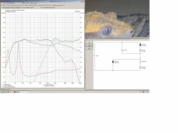
series x-o
original x-o
series x-o
original x-o
- Status
- This old topic is closed. If you want to reopen this topic, contact a moderator using the "Report Post" button.
- Home
- Loudspeakers
- Multi-Way
- TQW lam build progress