Personally I wouldn't use any protection unless i had an insanely powerful amplifier connected to the driver in an application like a club PA system where high spl operation is the norm - for home use this usually isn't required and is quite likely to degrade the performance of anything it is connected to. (You'd also probably be deaf before the driver failed.)
More details please: driver, amplifier, frequency range, spls, size of room...
More details please: driver, amplifier, frequency range, spls, size of room...
Oh, it would work all right. It would work by destroying the power amplifier when excess voltage switches on the triac. Some amps would be intelligent enough to shut down when they see the output being shorted - it would look to the amplifier like a speaker cable intermittently shorting out. Other amps would fail outright, taking care of the problem of excess loudness once and for all.
The circuit is there to "protect" the drivers from drunk, brain-damaged or hearing-impaired DJs who twist the knobs to 11. If the amps had moderately effective overcurrent protection, you'd hear this horrendous screech as the amp rapidly cycled on and off at full power. Smarter amps would gently decrease the power, or maybe go quiet for several minutes, waiting for the condition to clear. Other amps would go silent forever. It would all depend on how the overcurrent protection circuits worked, for the triac will surely trigger them. That's what it's designed to do.
Needless to say, this has nothing to do with hifi, but with operator abuse. The smart way to protect the drivers (in high-level PA use with careless operators) is with intelligent limiting and compression, tailored to the driver's thermal and excursion limits, and part of an active crossover circuit. This circuit is not the smart way. At best, it would generate a horrendous screech when the diodes and triac trigger on, and at worst, the amplifier would be provoked into bursts of full-power oscillation. Keep that up long enough, the amplifier might even catch on fire. That would certainly liven up an evening at the dance club.
Last edited:
Oh, it would work all right. It would work by destroying the power amplifier when excess voltage switches on the triac. Some amps would be intelligent enough to shut down when they see the output being shorted - it would look to the amplifier like a speaker cable intermittently shorting out. Other amps would fail outright, taking care of the problem of excess loudness once and for all.
The circuit is there to "protect" the drivers from drunk, brain-damaged or hearing-impaired DJs who twist the knobs to 11. If the amps had moderately effective overcurrent protection, you'd hear this horrendous screech as the amp rapidly cycled on and off at full power. Smarter amps would gently decrease the power, or maybe go quiet for several minutes, waiting for the condition to clear. Other amps would go silent forever. It would all depend on how the overcurrent protection circuits worked, for the triac will surely trigger them. That's what it's designed to do.
Needless to say, this has nothing to do with hifi, but with operator abuse. The smart way to protect the drivers (in high-level PA use with careless operators) is with intelligent limiting and compression, tailored to the driver's thermal and excursion limits, and part of an active crossover circuit. This circuit is not the smart way. At best, it would generate a horrendous screech when the diodes and triac trigger on, and at worst, the amplifier would be provoked into bursts of full-power oscillation. Keep that up long enough, the amplifier might even catch on fire. That would certainly liven up an evening at the dance club.
It shouldn't destroy the amp since there is a 4 ohm resistor in series with the driver and another in series with the triac which is across the driver - so the minimum load will always be > 4 ohms, this shouldn't be a problem for any decent modern amplifier.. This sort of overdrive protection circuit or variants of it are sometimes found in clubs (discos) and some roller rinks where the average spl levels are rather high. (Not to mention certain brands of home mid-fi) Attenuation would be on the order 6dB or so when the circuit kicks in, but there is nothing subtle about the way it sounds. (Bad) I've worked on a somewhat more sophisticated version at a former employer to provide VC overheating protection. (Attempt to replace light bulbs, ultimately the bulbs stayed due mainly to cost considerations.)
Last edited:
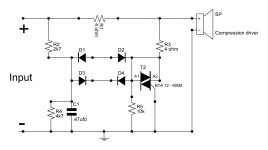
I have seen the circuit attached is used in crossover. It is used for compression driver protection. I like to know does it really work?
Are you runing active?? Are you using them at home?? If you are all you need to do is drop in a series capacitor to keep any turn on DC thumps out of the drivers. That should be all the protection you need unless you want to destroy you hearing. Active you should never get anywhere near a typical compression drivers power rating. Certainly not in your home unless it's the size of a Gym.
Rob
")
Last edited:
There was mistake in schematics.
Waiting for guidance from fellow members.
Note that there is still a mistake in the schematic. A1 should be connected to the return (ground) and the control electrode connected to the control circuit. The diodes are drawn incorrectly as well. They cannot conduct as connected.
Last edited:
For home use I would not recommend the use of any protection circuit unless you like your music really loud and have chosen a driver with insufficient sensitivity for the spl levels you need to achieve. This is brute force approach that is not meant to sound good, but to protect the driver in the event of gross overload.
Maybe the diodes are zenering, although there is probably a good diac for the job. I can't explain the gate connection.
The circuit would sound terrible, and if you could hear at all would probably force you to turn it down instantly. So I guess it could work. Not much of a limiter though, a divider instead of course, dropping only a couple dB when fired, and a little even when it's not. Why not arrange for the same voltage threshold to drive a nice white LED. Same end result, less funny noise.
The circuit would sound terrible, and if you could hear at all would probably force you to turn it down instantly. So I guess it could work. Not much of a limiter though, a divider instead of course, dropping only a couple dB when fired, and a little even when it's not. Why not arrange for the same voltage threshold to drive a nice white LED. Same end result, less funny noise.
Last edited:
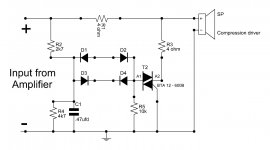
I will recheck & post tomorrow.Note that there is still a mistake in the schematic. A1 should be connected to the return (ground) and the control electrode connected to the control circuit. The diodes are drawn incorrectly as well. They cannot conduct as connected.
Thanks for guidance to fellow members.
- Status
- This old topic is closed. If you want to reopen this topic, contact a moderator using the "Report Post" button.
- Home
- Loudspeakers
- Multi-Way
- Compression driver protectioon?