I think I played it TOO LOUD!!
Well, I was testing to see how loud I could play the drivers...
...not!
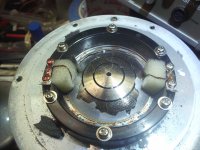
This is what happens when they are run way too hard too long in pro PA/SR service! There is salt air corrosion showing on the phase plug that is not normally there is from being stored improperly. Not me, I got them that way. The VC is fine... any ideas on how to release the glue that holds the paper former to the aluminum dome without soaking through the paper and releasing the VC bonding??
Well, I was testing to see how loud I could play the drivers...
...not!
This is what happens when they are run way too hard too long in pro PA/SR service! There is salt air corrosion showing on the phase plug that is not normally there is from being stored improperly. Not me, I got them that way. The VC is fine... any ideas on how to release the glue that holds the paper former to the aluminum dome without soaking through the paper and releasing the VC bonding??
Attachments
Well, I was testing to see how loud I could play the drivers...
...not!
This is what happens when they are run way too hard too long in pro PA/SR service! There is salt air corrosion showing on the phase plug that is not normally there is from being stored improperly. Not me, I got them that way. The VC is fine... any ideas on how to release the glue that holds the paper former to the aluminum dome without soaking through the paper and releasing the VC bonding??
Maybe with a small controlled blow torch flame from a gas-driven soldering iron. What dome will you choose to glue on?
Last edited:
Hylle, look back in the thread, think there are pix. I will post a closeup of the suspension element's failure mode shortly. This is a *standard* approach to a spider that was used early on in speaker design, They used a "Z" shape (more or less) to connect to the VC neck in cone woofers. Jensen used this as did many other pre-WWII mfrs. Here it is adapted to a smaller size and larger number. You can find the patent for the drivers online, although that does not spell out reasons for using this design for the surround. It's a compliance, it moves. 
What are you interested in?
Rewind, the phenolic dome will be indestructible but will not likely give the same performance as the stock diaphragms. I think these are the same size as Altec 288 (and that line) and will drop in place - not sure if the mounting holes line up or not.
A blowtorch flame? Nah, that will burn through the paper former and the thin aluminum diaphragm.
It would need to be a chemical method.
I have at least one diaphragm with bad VC, so if I could transplant the "good" dome onto the good VC, I'd be set! Probably not a practical thing to do. Then too, I would have to find a new glue to assemble the whole thing, maybe even need to make some sort of fancy jig since the orientation between the two is reasonably critical, and you can't exactly grab the dome since it is very thin and will dent and ding...
Bear,
I would suppose that the actual adhesive is an epoxy resin system of some sort. One chemical that would work that I know of is methylene chloride. You would have to be careful that it did not wick up into the former and also dissolve the voice-coil bond but it you are careful this could work. It does take a while for this to happen, not in seconds I must say. There are also specific solvents made for dissolving an epoxy used for encapsulated part but I am not sure what they are right now. You are also correct that the alignment and positioning of the diaphragm would be near impossible without the proper fixturing, near impossible I would think in a compression driver. But you could make a simple mold off the diaphragm assembly that has a burned voice-coil and use that to align the assembly when you put them back together. RTV silicone could be used to do that.
I would suppose that the actual adhesive is an epoxy resin system of some sort. One chemical that would work that I know of is methylene chloride. You would have to be careful that it did not wick up into the former and also dissolve the voice-coil bond but it you are careful this could work. It does take a while for this to happen, not in seconds I must say. There are also specific solvents made for dissolving an epoxy used for encapsulated part but I am not sure what they are right now. You are also correct that the alignment and positioning of the diaphragm would be near impossible without the proper fixturing, near impossible I would think in a compression driver. But you could make a simple mold off the diaphragm assembly that has a burned voice-coil and use that to align the assembly when you put them back together. RTV silicone could be used to do that.
I'd be concerned about peel-off of a silicone or latex molding material, but it is worth considering, since I may have more than one dead diaphragm...
The glue looks to the eye not like an epoxy, but that can be deceiving.
I would have to make some inquires to try to find out what the glue of choice was in the 1980s for paper to aluminum VC bonding... or what it is now. Wonder if they are using UV cure or cyanoacrylate now...
UV cure would be nice, you can dork it until the last moment. Otoh the parts need to have good mechanical contact... tricky bit building these diaphragm assemblies.
_-_-
Ya Bear I have to do this same thing on a beryllium dome tweeter project that I am working on. The tooling to align the dome and voice-coil and the surround will have to be very critical and the dimensions will be in the .0001" area. The bonding pressure is very critical also as you don't want to squeeze out all the adhesive. CA adhesives are fairly easy to debond and any model shop will have those debonders. I doubt that the older diaphragms are anything like a ca adhesive, perhaps some phenolic adhesives could be used but they would have been very rigid and brittle. Not great for sound I wouldn't think. Epoxy has been used for a long time before much else became available that would take the high temperatures.
Bear,
If you purchase a RTV silicone that is made for tooling application it will not leave any residue behind. That is the beauty of these materials and I have made both parts and molds from this type of material. The only real problem is that this material is rather expensive. It used to be all from DOW but they got out of the business and now there are many others who have stepped in to take over this business. Check out BJB Enterprises I think they sell this material. Local tooling suppliers will also have this type of material. It is not the same as the stuff you get at the hardware store, it is a two component system that you have to mix and if possible put in a vacuum chamber to de-gas. If you decide to do this let me know and I will walk you through some of finer points how to do it.
Steven
Steven, cool. I actually have a carton of similar stuff, but it is incredibly out of date code, was that when I got it very cheap! Who knows if it still works or not! I could try it out on scrap and see.
Bleed into the suspension fingers would be a problem...
Not sure I want to get too deeply into the issues as I have enough drivers on hand for myself at the present time.
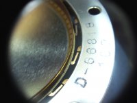
The cyanoacrylates I don't think will handle the local temps, nor will most epoxies. A phenolic based glue is what it looks like to my eye now that you mention it. I think this stuff started out slightly soft but has become less so over decades of time. I can shoot a closeup image, maybe you or someone will recognize it.
@Hylle, there is an opening and path through the fingers, but it is not exactly directly from the front to the back. It is a bit longer than that. The path length works at higher frequencies against cancellation. Also the energy and pressure that can pass through is limited compared to the direct energy of the diaphragm. And, actually this is part of the design idea, where the control of the diaphragm is mostly from the air in the rear chamber. It is supposed to (according to the patent, and Meyer's printed materials) make for a more linear and less distorted output - the two halves of the sinewave cycle being more equal when loaded on a horn compared to the way a standard compression driver operates. Sinewave and program material both.
I presume that today, IF one wanted to correct for this, one could predistort the input signal using DSP and get much the same effect or better. But that was the idea.
Bleed into the suspension fingers would be a problem...
Not sure I want to get too deeply into the issues as I have enough drivers on hand for myself at the present time.
The cyanoacrylates I don't think will handle the local temps, nor will most epoxies. A phenolic based glue is what it looks like to my eye now that you mention it. I think this stuff started out slightly soft but has become less so over decades of time. I can shoot a closeup image, maybe you or someone will recognize it.
@Hylle, there is an opening and path through the fingers, but it is not exactly directly from the front to the back. It is a bit longer than that. The path length works at higher frequencies against cancellation. Also the energy and pressure that can pass through is limited compared to the direct energy of the diaphragm. And, actually this is part of the design idea, where the control of the diaphragm is mostly from the air in the rear chamber. It is supposed to (according to the patent, and Meyer's printed materials) make for a more linear and less distorted output - the two halves of the sinewave cycle being more equal when loaded on a horn compared to the way a standard compression driver operates. Sinewave and program material both.
I presume that today, IF one wanted to correct for this, one could predistort the input signal using DSP and get much the same effect or better. But that was the idea.
Very good description by JLH. I guess he would argue that a Goto S-150 is too big for the JA6681B. We shall see what it can produce with a modified Atlas.
Wrong again. The Ja6681B sounds wonderful in a Goto horn.
What is the fs of the JA-6681B?
Hello,
Fs of the JA-6681B is around 215Hz but slightly dependant on the horn used.
Best regards from Paris, France
Jean-Michel Le Cléac'h
http://www.azurahorn.com/6681_on_160.pdf
Hello,
This means that this driver can be used in large format horns for home use but this doesn't mean that it cannot be used with small horns.
But this driver is so good on voices that it would be a shame to refuse to use it in the low mid with a large format horn.
Best regards from Paris, France
Jean-Michel Le Cléac'h
Rewind, i am interested in your Yamaha project as your xover point is close to what is practical for me. Mitt vardagsrum är smalt so I cant fit huge horns there. After some reading about voice characteristics I, in theory, think that 400-500 Hz would do as the low xover point. Such horns would get reasonable in size. The trouble then is to find a bass that matches this horn. Protruding horns are a problfm but not big walls, so maybe OB bass could be something? Any thoughts?
- Home
- Loudspeakers
- Multi-Way
- Info on the Yamaha JA-6681 compression driver