Hello,
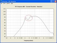
i have a question about conical horns. As seen in the picture, they often have a big dip in their frequency response at the lower end of their bandwidth - or maybe one should speak of two peaks. I would like to know if there are solutions to flatten the response, filling in the dip. Playing around in hornresp i have not found an obvious solution, except making the horn way to big to be usefull.
Kind regards,
Mathias
Attachments
Sorry I can't help you directly but the tweeter in classic Tannoy DCs ('pepperpots') is a conical horn which behaves very much like a CD horn (dispersion is a fairly constant 90deg from xover to 10kHz and it also requires 6dB/oct boost from around 5kHz up to make it usable in a 2way).
Exactly in the region you marked however it has a peak rather than a dip which Tannoy fixed with a notch filter. Removing that notch results in that horrible 'horn honk' so typical of nearly all '80s horn-loaded p.a. systems.
I always assumed that it caused by non-linear loading efficiency.
Either way since the problem was very common I'm thinking if you put a nice vintage AlNico driver on an actual horn the FR might even out a bit in real life.
If you're lucky…
Thats an interesting anecdote, Charles. I would take a peak allways over a dip, since filtering something away is better than having to amplify. The dip isnt present in a exponential horn and steadily grows when its morphed into a conical one by rising the flare rate T. So i guess its inherent in the conical horn shape.
If someone else has a clue or even a wild guess, please chime in and let me know.
If someone else has a clue or even a wild guess, please chime in and let me know.
The Hornresp model of a conical doesn't include a round-over at the mouth which helps reduce reflections back toward the throat, aka horn honk. The reflections cause peaks and dips at certain frequencies. I'm not too experienced with Hornresp but I think you can add a rounded or exponential section after the conical section. Give it a try.
Great idea catapult ")
I tried it and it could reduce the dip to about 2db. Although hornresp now tells me that a value called CIR is in a no good range for one horn segment, which means the results of the sim could be less accurate - i just hope that the loss in accuracy isnt the only thing that made the dip smaller.
So, if the dip is a result of mouth reflections, wouldnt adding foam for damping add even more to a balanced sound?

Lumpy response is a symptom of horn resonances, caused by the wave bouncing up and down the length of the horn, kind of like a fast echo.
To smooth it, you need a good acoustic impedance match either at the mouth and/or at the throat to avoid reflection. (It doesn't have to be matched at both ends)
At the mouth, the match will be good above a frequency determined by it's size. A larger diameter will be good down to a lower frequency.
With an exponential horn you can get a good match between driver and throat at lower frequencies - above the horn's cut-off, but below the driver's mass roll-off.
Conical horns are a bitch to match properly at the throat because they don't present a constant acoustic load to the driver - it drops fast with reducing frequency.
So...
With exponential (or similar) horns, you can get a nice smooth response when there's a good match between driver and throat at lower frequencies and a good match at the mouth at higher frequencies, with a bit of overlap.
But...
A conical horn with a small mouth is almost sure to give grief at low frequencies as the horn's badly matched at both ends.
Anyway, there's a couple of other things to play with aside from horn shape:
With cone drivers, the back chamber volume has a major effect on low frequency response. (With compression drivers, you're stuck with what you're given)
Any kind of crossover network (e.g. a series capacitor) will also have an effect on resonances - usually for the worse, but maybe worth experimenting with anyway. That's because it changes the driver's mechanical impedance, and therefore affects matching to the throat.
Hope some of that makes sense.
Cheers - Godfrey
and/or an exponential section before the conical section.... I think you can add a rounded or exponential section after the conical section. Give it a try.
That's what Earl Geddes ("gedlee" on this forum) does with his horns. The whole horn's filled with foam. Apparently they're very good.... wouldnt adding foam for damping add even more to a balanced sound?
Great idea catapult
I tried it and it could reduce the dip to about 2db. Although hornresp now tells me that a value called CIR is in a no good range for one horn segment, which means the results of the sim could be less accurate - i just hope that the loss in accuracy isnt the only thing that made the dip smaller.
So, if the dip is a result of mouth reflections, wouldnt adding foam for damping add even more to a balanced sound?
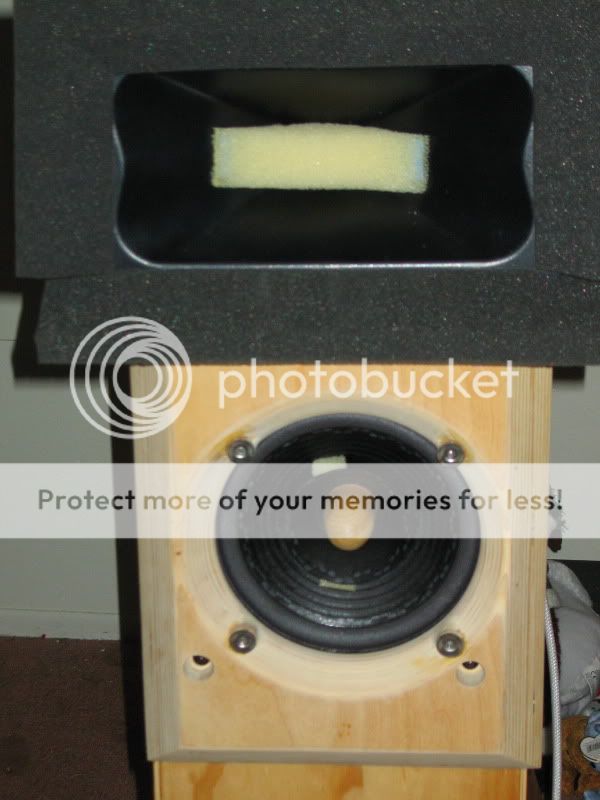
I added a foam collar, following a beveled profile around the mouth termination of the horn. Open cell foam being what it is is a combination of absorbtion and reflection, so in some respects this acts as an extension, and some as just a diffraction control device. In any case, I got about 1.5dB average ripple smoothing at the bottom end of the response by incorporating the collar you see below. Nothing to sneeze at!
There's a definite improvement in smoothness and clarity with the foam in place. Honk? Haven't heard any yet, though I'm well-loaded with reticulated foam in the throat and the foam termination of the horn.
Cheers - Godfrey
Thanks, i think it does. So, the roundover seems to work as an impedance match at the mouth. And at the throat nothing can be done without loosing the constant directivity of the horn.
Thats pretty much what i was thinking about. Until now, i only thought of foam as a HOM reducing device, while this use is more like room treatment for mode smoothing. Probably it works allways in both ways.
Have you tried using a roundover at the mouth instead of foam? Or maybe a combination of both?
No, I didn't try a roundover. Certainly this method introduces beamwidth restriction at frequencies around the horn cutoff, both via reflective/absorbtive functions, in addition to reducing and absorbing diffraction. The roundover would do the same but by virtue of increasing the horn size, also extends useable bandwidth down. The foam is a lossy technique, the roundover would be expected to extend loaded bandwidth.
Hi Mathias
Here's a article on DIY waveguides: Practical DIY Waveguides - Part 1
I haven't waded through the whole thing yet myself, but it looks interesting.
btw, What kind of driver was used for that plot in post 1?
High-end response looks really good for a cone, or is it a compression driver?
Cheers - Godfrey
I thought about doing a quasi-horn out of open cell foam,but thought better of it.
How sayeth the board?
It makes a lot of sense if you don't need the additional efficiency provided by horn-based directionality. I'm a big fan of efficiency but it's not always worth prioritizing over other things.
You do have to be aware that absorbtion is not entirely linear WRT frequency and intensity.
I've used similar methods to help with directivity in other designs to great effect but it does take experimentation and effort.
- Status
- This old topic is closed. If you want to reopen this topic, contact a moderator using the "Report Post" button.
- Home
- Loudspeakers
- Multi-Way
- Conical Horn Dip