An externally hosted image should be here but it was not working when we last tested it.
An externally hosted image should be here but it was not working when we last tested it.

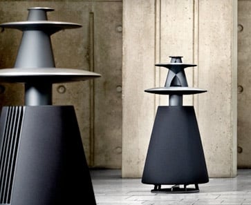
Canon S-35 loudspeaker | Stereophile.com
Hi, worth a look and read, rgds, sreten.
Last edited:
I've been thinking about these SAW lenses for a few years now, and had a 'Eureka' moment today.
Basically, I think I figured out how they work.
More importantly, I believe there's a way to improve them, and also a way to make them full range.
Here's my 'hypothesis' on these lenses:
First off, these lenses work in the same way that a horn does.

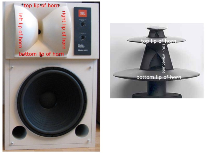
In a constant directivity horn, like these Electrovoice HR90s, there are multiple stages. The first stage provides gain; the second stage defines the horizontal and vertical beamwidth; and then the third stage 'flares out' to provide a smooth transition to the room.
The lenses from Sausalito Audio Works function in a similar fashion; the major difference is that they don't *look* like a horn, and there's a reflector built into the device.
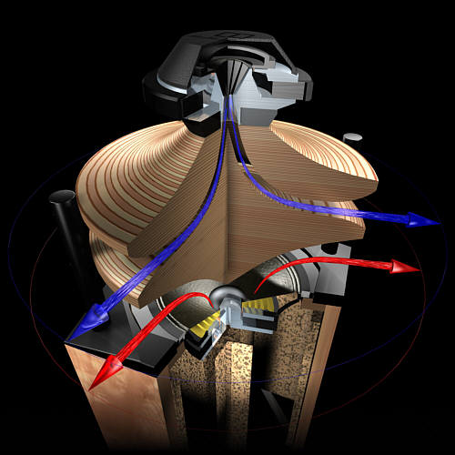
Here's a pic from the Beolab 5, where I've tried to illustrate the various stages of the device.
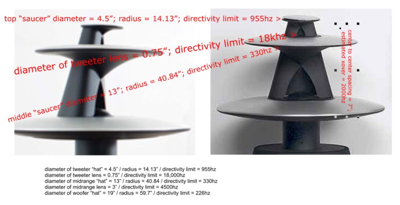
The first stage is the one that everyone notices; that intriguing 'teardrop' lens. What's interesting is that once you do the math, you'll find that the lens isn't doing a whole lot!
Whether it's a horn or a lens, the directivity of a device is dictated by it's size. And based on the diameter of the lens in front of the Beolab 5 tweeter, it's only working above 18,000hz! This calculation is based on it's diameter; with a width of just 0.75", the lens is basically invisible to frequencies below 18khz.
Surprisingly enough, the baffle *behind* the tweeter is playing a bigger role here. Wit a diameter of approximately 4", the baffle *behind* the tweeter is constraining it's output from 3375hz and up.
The 'saucers' above and below the tweeter aren't just for show; they're functional. The saucers act like a radial horn, basically redirecting the energy of the tweeter away from the floor and from the ceiling.
And due to their significant size, they have this effect across the entire bandwidth of the tweeter. As show in the illustration, the "top" saucer works from 955hz and up, while the middle 'saucer' works from 330hz and up.
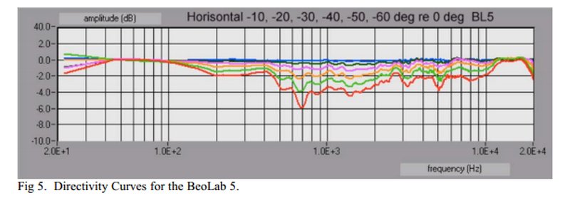
Here's the polar response of the BeoLab 5, showing that the lens itself doesn't work over a wide bandwidth. (Note how the directivity improvement in the tweeter only spans a fraction of an octave.)
IMHO, the most important element of the design isn't the lens; it's the saucers and the baffle behind the drivers. The saucers are acting like a radial horn, preventing the drivers from radiating towards the floor and the ceiling. The baffle behind the drivers prevents them from radiating towards the back of the room.
It's basically a radial horn; albeit one that looks great, and one that radiates low frequencies across the entire listening room. (Which reduces distortion, in the same way that increasing the size of the mouth does.)
Basically, I think I figured out how they work.
More importantly, I believe there's a way to improve them, and also a way to make them full range.
Here's my 'hypothesis' on these lenses:
First off, these lenses work in the same way that a horn does.
In a constant directivity horn, like these Electrovoice HR90s, there are multiple stages. The first stage provides gain; the second stage defines the horizontal and vertical beamwidth; and then the third stage 'flares out' to provide a smooth transition to the room.
The lenses from Sausalito Audio Works function in a similar fashion; the major difference is that they don't *look* like a horn, and there's a reflector built into the device.
Here's a pic from the Beolab 5, where I've tried to illustrate the various stages of the device.
An externally hosted image should be here but it was not working when we last tested it.
The first stage is the one that everyone notices; that intriguing 'teardrop' lens. What's interesting is that once you do the math, you'll find that the lens isn't doing a whole lot!
Whether it's a horn or a lens, the directivity of a device is dictated by it's size. And based on the diameter of the lens in front of the Beolab 5 tweeter, it's only working above 18,000hz! This calculation is based on it's diameter; with a width of just 0.75", the lens is basically invisible to frequencies below 18khz.
Surprisingly enough, the baffle *behind* the tweeter is playing a bigger role here. Wit a diameter of approximately 4", the baffle *behind* the tweeter is constraining it's output from 3375hz and up.
The 'saucers' above and below the tweeter aren't just for show; they're functional. The saucers act like a radial horn, basically redirecting the energy of the tweeter away from the floor and from the ceiling.
And due to their significant size, they have this effect across the entire bandwidth of the tweeter. As show in the illustration, the "top" saucer works from 955hz and up, while the middle 'saucer' works from 330hz and up.
Here's the polar response of the BeoLab 5, showing that the lens itself doesn't work over a wide bandwidth. (Note how the directivity improvement in the tweeter only spans a fraction of an octave.)
IMHO, the most important element of the design isn't the lens; it's the saucers and the baffle behind the drivers. The saucers are acting like a radial horn, preventing the drivers from radiating towards the floor and the ceiling. The baffle behind the drivers prevents them from radiating towards the back of the room.
An externally hosted image should be here but it was not working when we last tested it.
It's basically a radial horn; albeit one that looks great, and one that radiates low frequencies across the entire listening room. (Which reduces distortion, in the same way that increasing the size of the mouth does.)
Last edited:
Its seems similar to the Duevel speakers. With a horn/waveguide combination.
An externally hosted image should be here but it was not working when we last tested it.
Last year, I built new SAW-based lenses for my Alesis dome tweeters.
Experience has taught me that stiffer material is better and I think that these glazed ceramic reflectors/baffles/horns work very well.
The main benefits, which have kept me interested in improving my speakers, are the wide sweet-spot and increased efficiency.
Increased efficiency... to me, means: any speaker that moves is distorting, so, if it is barely moving then that means it's not distorting as much as it could.
My SAW loaded Alesis domes are throttled way back.
Wide dispersion is a good thing. It just sounds right to me, but these are my ears and the sound is decoded by my brain... such as it is.
I've always liked the sound of dome tweeters in my SAW clones;
these ceramic sculptures sound the best, by far, to my ears.
You can see that they are not even close to an actual SAW clone, mathematically.
Go figure.
-Steve.
I
In a constant directivity horn, like these Electrovoice HR90s, there are multiple stages. The first stage provides gain; the second stage defines the horizontal and vertical beamwidth; and then the third stage 'flares out' to provide a smooth transition to the room.
This isn't strictly accurate- the first stage doesn't add meaningful extra gain, rather, it allows one to have a lower cutoff for a given mouth size, by making it deeper. With a "normal" conical horn, you're only about as deep as the radius, but with an extended throat and diffraction slot, you can keep the same 90 degree nominal pattern, while retaining the straight(ish) walls (constant directivity) and the smaller mouthsize for a given LF cutoff.
You seem to be under the impression that the throat section acts as one horn, and that the SPL into the narrow pattern defined by that profile is retained after the transition to the wider pattern. This is not the case- the diffraction slot spreads this energy across the coverage pattern, and thus for any given point within this larger pattern, the SPL is lower than it would be in a pure tiny-angle horn like the throat.
Easy enough to test this- find a frequency at which a horn is loading well (well above cutoff), then add a long tube between the driver and horn throat. You'll see boost in the cutoff region, but not at the frequency where the original horn was already fully functional.
This isn't strictly accurate-
Lets be clear that almost all of the gain comes from the compression ratio which happens even before the horn and phase plug. The horn itself is simply a means to better couple the area ratio decrease into the sound field. There isn't necessarily any gain at all.
For example, a direct radiating tweeter on a waveguide only sees a very small increase in power output, the gain comes almost completely from the narrower directivity. The SAW would likely have no gain at all.
Its seems similar to the Duevel speakers. With a horn/waveguide combination.

Up until yesterday I would've agreed!
But it's actually closer to a monopole version of John K's NAO Note II:

In the NAO Note II, we have four frequency ranges. The width of the baffle is approximately twice the width of the piston.
The width of the baffle is very important. Although it's not immediately obvious, the baffle of a loudspeaker acts as a waveguide, albeit one that radiates into 180 degrees.
Here's a pic I made, which illustrates how the midrange in the Beolab5 radiates. In this pic, I am only showing the horizontal radiation. If you look at the speaker, the round shape might imply that the radiation is 360 degrees. But it's not. It's basically 180, similar to what the NAO Note II would radiate if it was a monopole. The reason that it radiates in 180 and not 360 is because of the small baffle that's behind the drivers, a baffle that's basically twice as wide as the radiator. That's just big enough to restrict radiation into the forward lobe.

^^ In the illustration above, I have used the wavefront simulator in Hornresp to demonstrate that the Beolab radiates into 180 degrees, not 360. The illustrations is based on the midrange in the Beolab 5, which is a 3" dome. Here's some obsevations about the radiation:
1) The midrange is 3" in diameter. 4500hz is 3" long. When the sound is 4500hz it's radiated towards the listener. The top right sim from hornresp shows this; it's only radiated into the forward lobe. The wavelengths are small enough that they're constrained towards the listener.
2) The baffle behind the mid is 5" in diameter at it's midpoint. 2700hz is 5" long. When the sound radiated by the midrange is 2700hz, it's still radiated into the forward lobe., toward the listener.
3) Below 2700hz, the baffle in the Beolab5 is no longer constraining the radiation of the midrange. This is because the wavelengths exceed the width of the baffle. Basically the sound 'wraps around' below 2700hz. The simulation from Hornresp illustrates this. At 1000hz we see that the midrange is now radiating into 360 degrees.
Note that these statements only apply in the horizontal axis. In the vertical axis the directivity is completely different. For instance, the platter below the midrange is 19" in diameter, and that's big enough to keep anything from 710hertz and up from 'bouncing' off the floor.
In summary, in the horizontal axis the output of the midrange is restricted into the forward lobe. From 2700hz and down, the radiation begins to broaden, until it's radiating in 360 degrees by the time it hits 1000hz. But the broadening happens gradually. I haven't been able to find anything that documents where the crossover points are, but my 'hunch' is that the baffle width tapers so that the radiation is always in 180 degrees at the crossover point. For instance, the midrange baffle is 5" wide at it's midpoint; but the center to center spacing between the mid and the tweeter is about 5.5". Assuming that the center to center spacing is one octave, then the xover point may be 2500hz. That's a good choice, as the baffle width of the mid keeps it's radiation consistent with the radiation of the tweeter.
There's a very interesting advantage to using a full circle for the platter, insted of the half circle used by the JBL radial horns:
I'll get into that in my next post.
(If anyone's curious, YES the hornresp sims are to scale. I counted the pixels by hand to be sure they're the correct size
") )
)Lets be clear that almost all of the gain comes from the compression ratio which happens even before the horn and phase plug. The horn itself is simply a means to better couple the area ratio decrease into the sound field. There isn't necessarily any gain at all.
For example, a direct radiating tweeter on a waveguide only sees a very small increase in power output, the gain comes almost completely from the narrower directivity. The SAW would likely have no gain at all.
Yeah I think the SAW lens itself - the 'eye shaped' cutout - isn't doing a whole lot. I'll have to build one to be certain, but the big 'lightbulb' went off when I realized that the platters below and above the drivers and the baffle behind the driver isn't just for show. The platters are narrowing the vertical directivity, and the baffle behind the driver is changing it from an omnipole like the Duvel to a monopole like a typical baffled speaker.
It was your comments and Dave Smith's comments over in the JBL M2 thread that clued me in to this. Looking at the polars of the JBL biradial horn from the 80s, it occurred to me that the 'horn' doesn't necessarily need to be in the box, it can be 'outside the box.'
The pic above shows both speakers to scale, which makes it easier to appreciate how big the platters are. They definitely change the vertical directivity. The biggest platter is 19" in diameter.
is there "significant" cavity volume and thin walls? - or are they like Steve's ceramic lens?
The cavity in the SAW lens is supposed to work the exact same way as the reflector in a Paraline. It's designed to take the energy directed UP and turn it 90 degrees. The reason that it's not a straight line is that a straight line wouldn't keep the wavefront in phase; that curved line WILL. Or at least it's supposed to!
The reason I believe that the effect of the SAW lens is relatively minor is the measured response. We know the dimensions of the lens, so we know what frequencies it works at.
And based on it's dimensions, it should work at 18khz and up on the tweeter, and 4500hz and up on the midrange. In the measured response of the loudspeaker we see a 'narrowing' of the polar response at 5000hz and at 18khz. I think that's caused by the lens, but note that it's very very narrow in bandwidth.
So, long story short, my 'hunch' is that the lens isn't doing a whole lot. But the platters and the baffle, which seem completely cosmetic, ARE doing a whole lot acoustically.
As for the construction of the lens, it's aluminum. Likely hollow, as B&O uses aluminum hydroforming for some of their other speakers, makes sense they'd use it for their flaghsip. (Same way that aluminum bicycles get their crazy shapes.)
the baffle of a loudspeaker acts as a waveguide, albeit one that radiates into 180 degrees.
So a flat baffle is a waveguide? Than all loudspeakers have been waveguides forever? An expansion of the definition of a waveguide that now includes everything that has ever been made or ever will be made. Marketing will love that.
Lets pray they're not lookingSo a flat baffle is a waveguide? Than all loudspeakers have been waveguides forever? An expansion of the definition of a waveguide that now includes everything that has ever been made or ever will be made. Marketing will love that.
Patrick, following you on this... you have the table

OK, this is insanely rushed, but I made some quick and dirty horns using the ideas from the Beolab 5.
The top and bottom platters are about 14" wide by about 10" deep. (The platters are elliptical.) The driver is Dayton's DE250 clone. (D250P iirc?)
In order to keep the height down to a minimum, I'm using the actual body of the compression driver to reduce the volume in the center of the horn. There's a baffle to mask off the inside 5" of the horn.
All of this is fairly similar to the midrange in the Beolab5. Instead of using a 3" soft dome, I'm using a compression driver. In the Beolab the top and bottom 'platters' are asymmetrical; mine are symmetrical mostly because I was in a hurry. (I used the top of a crockpot as a template
)Probably the biggest change is that I'm not convinced that the SAW lens does a whole lot, so I used a simple 45 degree reflector instead.
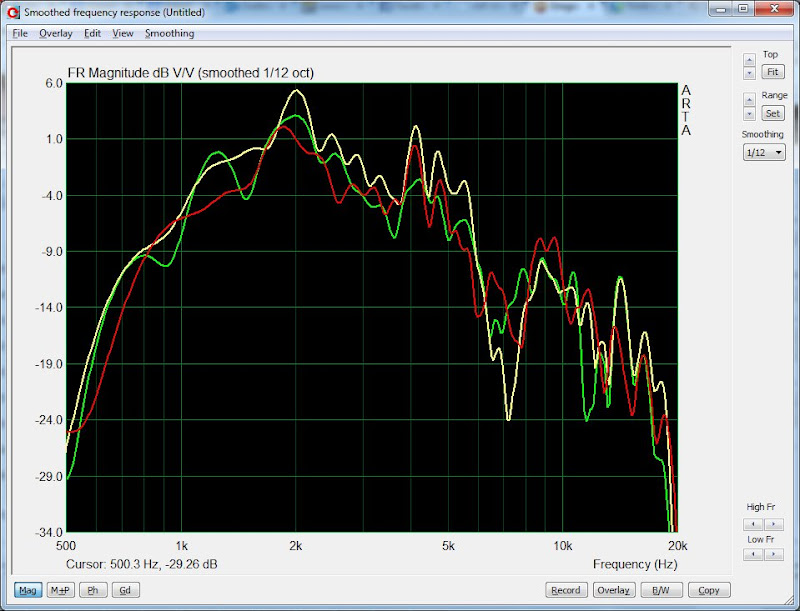
Here's the response 30 degrees off axis, 15 degrees off axis, and ON axis. Plus, the response 180 degrees off axis. (The back of the horn.)
Here's some observations:
1) Red is 30 degrees off axis, yellow is 15, blue is on axis. In the two octaves from 1500hz to 6000hz the three curves 'track' each other within +/- 3dB. So the beam width seems quite wide.
2) Green is the response 180 degrees off axis; IE the back side.
3) I was surprised that the the response to the back was so attenuated. Apparently the baffle really makes a big difference. I'd expected that by 2khz the response on the backside would start to rise, due to the sound 'wrapping around' the baffle. It doesn't seem to be doing that much; for instance the sound on the back side isn't close to the front side until 1khz or so. Perhaps I can get away with a smaller baffle? Or perhaps I could reduce a lot of the share edges on the baffle to improve the response?
I know the graph looks rough, but I really didn't invest any time at all in optimizing this thing. I think I could make a lot of improvements to it. It's very crude.
Surprisingly enough, it sounds quite good. I listened to a few things on it, and it had the same 'presence' that I noticed with a radial horn that I'd made with the BG Neo 3 a few weeks ago. But much more dynamic and extended in the highs.
Here's something you guys might geek out to.
This is the response from the *rear* of the horn, along with the first reflection off of the wall of my living room. (Since the horn was pointed *away* from me, the reflection is actually from the *front* of the horn.)
The reason I made this graph was because I was listening to the speaker, and the reflection was so similar to a speaker, it almost sounded like the sound was emanating from the wall of my living room. It was very odd. Like seeing something reflected in a mirror, but acoustically.
You can see the reflection is *very* true to the sound coming off the speaker.
I don't know if this is normal for loudspeakers to do this; I've never noticed it before.
Also, the reflected energy is the *green* graph. Due to the high attenuation at the rear of the speaker, if you point it away from you and aim it at the wall, the *reflected* energy is actually louder than the speaker itself! (Since it's forward lobe is so strongly pointed *forward*)
Last edited:
my 10 second coffee cup - uh waveguide, some years back maybe gave a tiny taste - if there's some cavity then its like a Karlson coupler - - this is a cool thread
An externally hosted image should be here but it was not working when we last tested it.
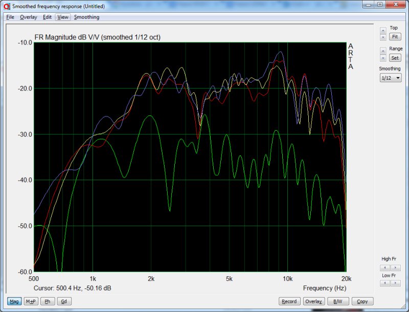
Here's some polars from the horn I did yesterday.
There's a big suckout at 3500hz.
3500hz is 3.85" long. So I'd expect some sort of reflection off of something that's 3.85" long, 1.92" long, or .96".

I used some clay to smooth out the 'step' on the edge of the compression driver. (Since the compression driver is literally inside of the horn.)
That basically smoothed out the suckout. The pic above shows the on-axis response, and 45 degrees off axis (horizontally). As we saw yesterday, the response off axis is fairly close to on-axis. It starts to beam more above 8khz; this is likely due to height of the horn. You might notice that the output above 13,500hz falls off-axis. There's nothing that can be done about this; it's due to the diameter of the horn exit (1".)
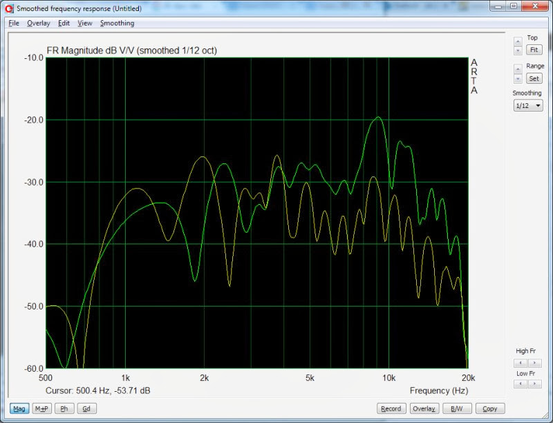
A big concern that I had was the vertical directivity. With a horn height of 1.7", I'd expect it to start beaming badly at 7941hz. (13500hz / 1.7")
Oddly enough, the measurements don't seem to show this. They're surprising consistent at various heights. The measurements above show the *vertical* response on axis (red), 22.5 degrees off axis (yellow) and 45 degrees off axis (green).
There *is* a suckout that spans nearly half an octave in the 22.5 degree curve.
A roundover would probably help a lot with this.
Last edited:
is there any cavity volume whatsoever between the aperture and the outside walls of these things? there's no way I'll ever see the speaker in person.

An externally hosted image should be here but it was not working when we last tested it.
is there any cavity volume whatsoever between the aperture and the outside walls of these things? there's no way I'll ever see the speaker in person.
An externally hosted image should be here but it was not working when we last tested it.
No; it's basically a two dimensional reflector like this:
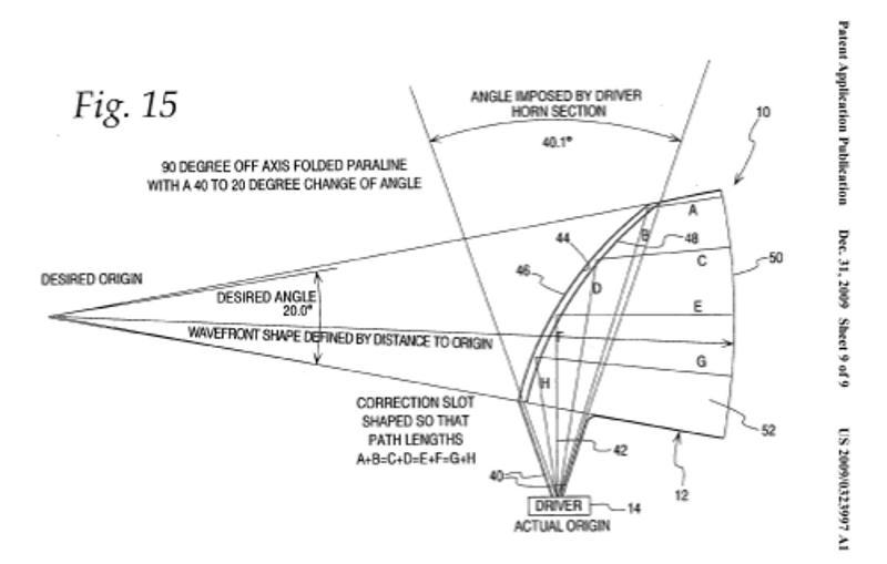
But the reflector has been rotated 180 degrees on it's center axis. (Pic above is from Danley's Paraline patent.)
Check out the Paraline patent to understand the Beolab better. Danley's patents are more forthcoming than B&Os
The company that invented and licensed the device has disclosed how it works on their own website, which is good reading too. (http://www.moultonlabs.com/images/pdfs/new_loudspeaker_design.pdf)Keep in mind that the dimension of the lens is very small, and due to it's small size it's only going to work over a very limited bandwidth.
Beolab5:
mine:
If you look at mine, the response below 13,500hz is similarily consistent on and off axis. IMHO, the SAW lens is only having a significant effect in the half octave above 14khz. And my compression driver is rolling off in a huge way by 16khz, so I'm not certain it's worth building the lens just to improve that last fraction of an octave.
But the platters and the baffle have a significant effect, for certain.

- Status
- This old topic is closed. If you want to reopen this topic, contact a moderator using the "Report Post" button.
- Home
- Loudspeakers
- Multi-Way
- Cloning a $3200 Speaker for $400