Hi all
I am wondering what the design guy was thinking when he did the filter I have in my speaker kit.
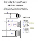
From DIY Audio and Video i have calculated the values shown on the first attachment, which is near what I have stuffed in my filter, exept that I have much larger C3 and much lower L2.
The values my filter have gives a more narrow passband and a kind of peak in the middle frequencys.
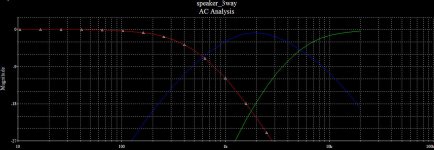
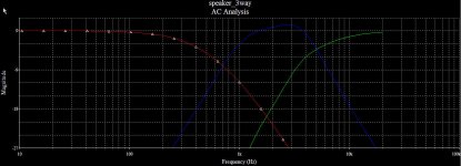
Second and last attachment shows the difference simulated. The elements are 8 ohm and are resistive in the simulation.
As I recall this filter was not tailored for a particular speaker setup. It was sold as a good three way 600/6000 filter.
Is this common and could it be a good thing?
One more thing. The capacitor to the tweeter C1 is in my case 2.2u and connected after C2 which in my case is 15u.
I am wondering what the design guy was thinking when he did the filter I have in my speaker kit.
From DIY Audio and Video i have calculated the values shown on the first attachment, which is near what I have stuffed in my filter, exept that I have much larger C3 and much lower L2.
The values my filter have gives a more narrow passband and a kind of peak in the middle frequencys.
Second and last attachment shows the difference simulated. The elements are 8 ohm and are resistive in the simulation.
As I recall this filter was not tailored for a particular speaker setup. It was sold as a good three way 600/6000 filter.
Is this common and could it be a good thing?
One more thing. The capacitor to the tweeter C1 is in my case 2.2u and connected after C2 which in my case is 15u.
Attachments
Last edited:
As I recall this filter was not tailored for a particular speaker setup. It was sold as a good three way 600/6000 filter.
Is this common and could it be a good thing?
A three way crossover with real drivers is fairly difficult even with modeling software. A stock 3-way board will have little or no chance of working properly unless the passbands of the drivers are wide, and they act as pure resistors. The odd values were probably chosen for economy and/or because that is what they had lying around - a 4mH inductor is expensive....
In fact those values (from the software) are the ones it gives from the box, L2 = 4.34 mH, C3 = 1.5 uF....
As I recall this filter was not tailored for a particular speaker setup. It was sold as a good three way 600/6000 filter.
Is this common and could it be a good thing?
One more thing. The capacitor to the tweeter C1 is in my case 2.2u and connected after C2 which in my case is 15u.
Why do you say: "It was sold as a good three way 600/6000 filter." It's just a tool, and makes us think you bought the xover from a shop or person. You can compare to other software utilities to find of it's own good or bad applicability (as a standard and mention the differences like you are doing). Many sound engineers tell you not to go there (calculators).
Another thing that does not work, very well, is the reverse polarity (or not) than needs to be checked and rechecked and it works with phase in simulations or in real life. Differences in phase are "very bad" and need to be addressed carefully or you will end up with the opposite you want to achieve; nulls, bad polar/directivity patterns and wrong frequency output.
Unless you use in your simulations complete data like Re, Le (and that's for a perfect driver), and then Fs, curves for output, phase, impedance (on a standard test box/panel or final enclosure), raw data files, and considering main differences in level, designing for perfect integration of phases and frequency output and differences in impedance, you can't get to a 3-Way design. This is just for simulation, then you adjust for real life and measure again, and enjoy.
Is better for you to post about your box, xover and drivers, so we know more of your xover problem.
Last edited:
It was bought from a shop nearly 20 years ago. Not many computer aided designs back then i guess.Why do you say: "It was sold as a good three way 600/6000 filter." It's just a tool, and makes us think you bought the xover from a shop or person.
I have, and everyone shows my filter is off. The thing is the outcome became a more narrow passband. A bit interesting. That's was why I asked here.You can compare to other software utilities to find of it's own good or bad applicability (as a standard and mention the differences like you are doing). Many sound engineers tell you not to go there (calculators).
Offcource you must use calculations to start with. With caution, as with any other calculators and simulators. The outcome doesn't get better then what the formulas you put in are, I know. Then there is the live tuning I understand have a large impact.
I have been fairly satisfied for years but I maybe say WOW! when I hear how it should beIs better for you to post about your box, xover and drivers, so we know more of your xover problem.
")
You mean I should post all my data and the schematic of the filter, so you, or someone else, take's hours of your free time, designing it for me?
I allready got some help from another thread about the box and bass elements.
Now it's the middle (closed one litre box) and the tweeter I wonder about. I think Ron E probably is close to the truth. There is no magic in my filter, just ignorance and economy thinking.
@Inductor
Yes, but now you are with me. It's allways tough to explain things short and clear
@panomaniac
Yes, as a "higher grade of confidence filter" (higher price) for generic 8 ohms speaker.
This is in the same time great, because now I can upgrade my system
The down thing is I can see that the bass drivers have some visible degration around the rubber rim. So in the near future I have to recalc. (OK More fun for the DIY man again )
In this area, as everyone else I have digged deep into, I once again can confirm.. The more you dig the more **** you find.
Thanks a lot for answers, taking up your time
Yes, but now you are with me.
It's allways tough to explain things short and clear @panomaniac
Yes, as a "higher grade of confidence filter" (higher price) for generic 8 ohms speaker.
This is in the same time great, because now I can upgrade my system
The down thing is I can see that the bass drivers have some visible degration around the rubber rim. So in the near future I have to recalc. (OK More fun for the DIY man again
)In this area, as everyone else I have digged deep into, I once again can confirm.. The more you dig the more **** you find.
Thanks a lot for answers, taking up your time
Yep, you at least need a good impedance sweep to start with. That way you can know what the actually filter functions are, if not the actual frequency response.
The values you give are odd, at least for the midrange. My sims show the graph below into a pure 8 ohm load. The real filter function is going to depend on your diver impedance plot.
The values you give are odd, at least for the midrange. My sims show the graph below into a pure 8 ohm load. The real filter function is going to depend on your diver impedance plot.
Attachments
I have allready measured the values of the elements...re:'you must use calculations to start with' - no, you must use measurements, hence Pano's question - to get an accurate crossover, you need to use the ACTUAL values of the drivers impedance at the crossover frequency...
Still My scenario I asked about is valid.
I will further input my exact values measured from the elements. And after that I have to measure anyway... after my "basic" "in the ballpark" simulation. I know, I know.
This will be my homework. I just refer to the first Q in this, my, thread. If it was somekind of "special cause" or "golden option" inside my filter. I have now understand that it wasn't. The rest I take care of myself. No problem.
I'm maybe not a noob when it comes to action after all
.That's the "Passive Crossover Designer" from the FRD Consortium. It runs in MS Excel. I love it. Free, too.
Passive Crossover Designer
Passive Crossover Designer
I got the tools now
Thank you panomaniac!
That was an amasing spreadsheet. Together with the Unibox spreadsheet, where I export my impedance curves to be imported to this "Passive Crossover Designer", I can see what I have now and what I need to do.
My old filters can really need some adjustments It's also great to be able to test different "what if" scenarios.
It's almost a pity I have decided to go with active filtering later on. I may go halfway though. Bi amping with a passive filter for the mid and tweeter.
Anyway, knowledge doesn't hurt, does it?
Thank you panomaniac!
That was an amasing spreadsheet. Together with the Unibox spreadsheet, where I export my impedance curves to be imported to this "Passive Crossover Designer", I can see what I have now and what I need to do.
My old filters can really need some adjustments
It's also great to be able to test different "what if" scenarios.It's almost a pity I have decided to go with active filtering later on. I may go halfway though. Bi amping with a passive filter for the mid and tweeter.
Anyway, knowledge doesn't hurt, does it?
You're welcome! The spreadsheet is a great tool. Just playing around with it will teach you a lot about how crossovers work.
If you can get the impedance curves of your drivers, you should plug them into the sheet. That allow you to see what the filter is really doing. It does not tell you the real frequency response, but it gets you closer.
If you can get the impedance curves of your drivers, you should plug them into the sheet. That allow you to see what the filter is really doing. It does not tell you the real frequency response, but it gets you closer.
At first I thought I had it all.
Now I see Í have problem with the spreadsheets. I can't save any setup. I can't load any of the examples in PCD without errors. I get errors 13 and 1004 All seems related to mid range driver calculations.
I'm running Office 2007 with all upgrades Win XP and SP3.
Ohh if something could be easy and fun all the way
************* time goes by ... *********
Just before I pushed the submit button on this reply, I gave my old Excel 2003 a chance. Installed beside my 2007 installation.
Now it seems to work.
Why isn't Office backward compatible? This is a PITA
Hope someone else can get use of my findings.
- Status
- This old topic is closed. If you want to reopen this topic, contact a moderator using the "Report Post" button.
- Home
- Loudspeakers
- Multi-Way
- Passive filter with odd values. Why?